XO FLEX dental unit with red patient chair

XO FLEX 2020 EDITION

As a dental practice owner you expect a high return on your equipment investment.
XO CARE has almost 70 years of experience with manufacturing of extraordinary dental treatment solutions.

XO FLEX 2020 edition grows out of this long design and manufacturing tradition.

Read the chapters below and learn more about your next dental unit.

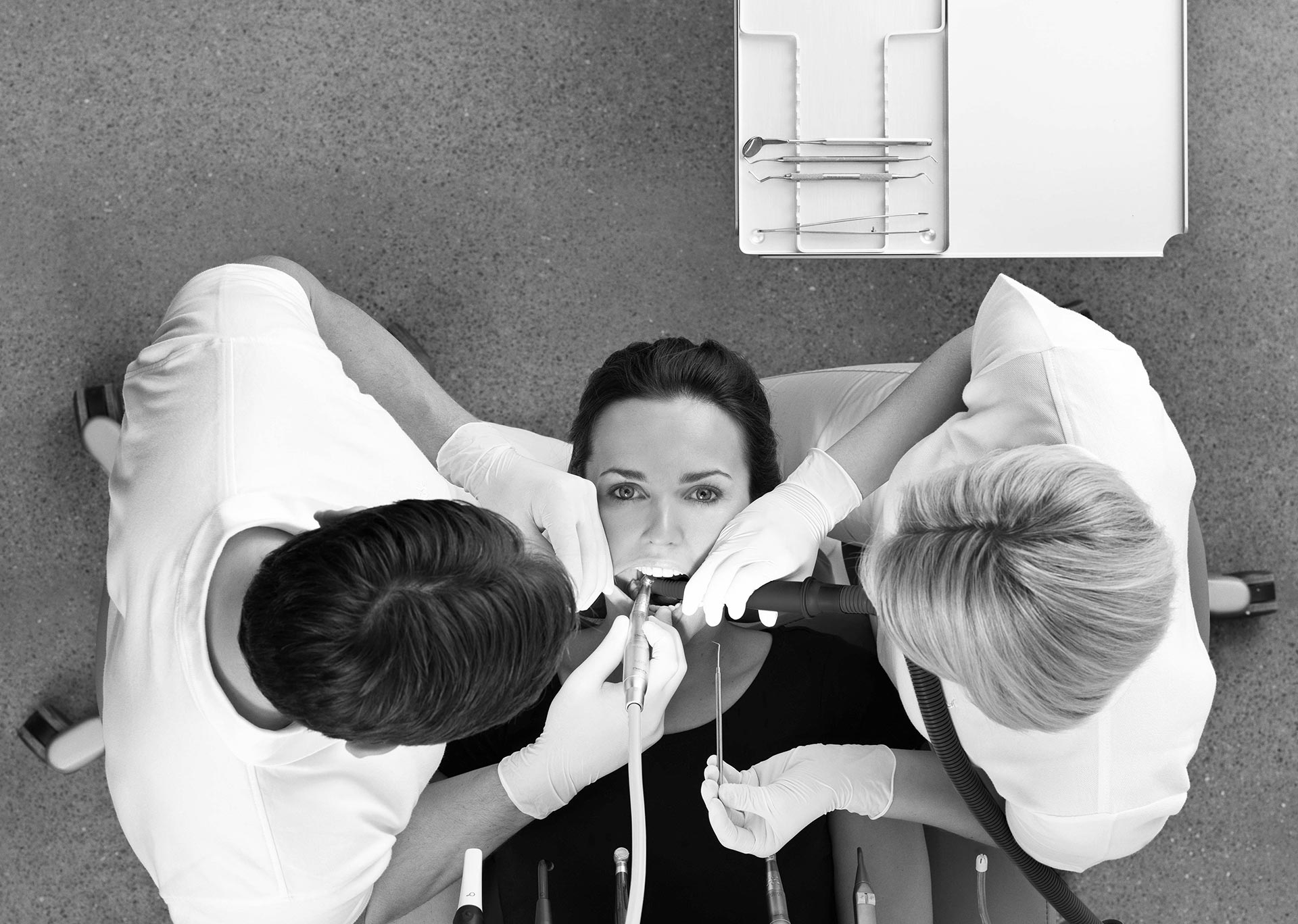
Efficient dental team work with over the patient instrument delivery system

Link

Link

HIGHEST QUALITY DENTAL TREATMENTS

XO empowers you to perform the very best dental treatments, enabling you to make full use of your skills and expertise. XO’s solutions allow you to focus on the working area in the oral cavity, improve management of the quality of treatment and apply your own individual settings.

Learn how XO FLEX allows you to perform perfect treatments

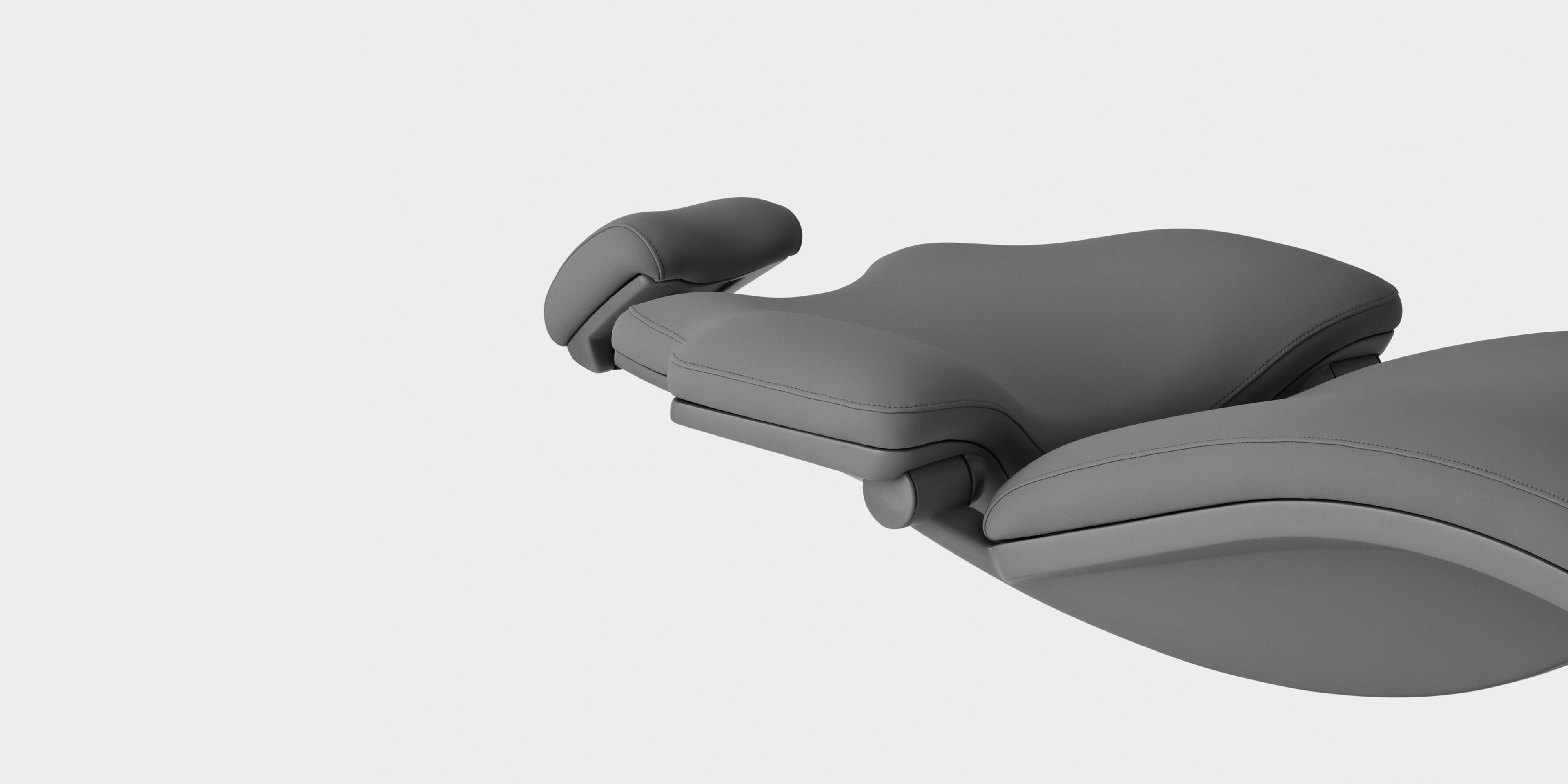
Comfortable dental patient chair

SAFE AND CALM PATIENTS

We understand and recognize how very important it is that your patient remains calm throughout treatment. To this end, XO's equipment is designed to be safe and comfortable and to help you gain the complete confidence of your patient.

Learn how you can provide the best care to your patients

blue dental unit design

MAXIMUM PRODUCTIVITY

Our objective is to help you increase the value of your equipment investment by saving you time and money, giving you maximum uptime and providing an attractive working environment.

Learn how XO FLEX will help you profit

XO Flow User Guide

XO FLOW

USER GUIDE


10%

CONTENTS

1EXTRAORDINARY DENTISTRY

2Operation

2.1General

2.2Switch the unit on and shutdown

2.3Stand-by & automatic power down

2.4Foot control

2.4.1Function

2.4.2Configuration

2.5Instrument bridge

2.5.1General

2.5.2Instrument bridge working position

2.5.3Working with balanced instruments

2.5.4Instrument bridge parking position

2.6Dashboard

2.6.1Information bar

2.6.2Lock dashboard and navigator button

2.6.3Patient chair menu and unit menu buttons

2.6.4Vertical side menus

2.6.5Instrument displays

2.6.6Instrument selection indicators

2.6.7Instrument control windows

2.7Instrument control

2.7.1Selecting and activating an instrument

2.7.2Monitoring and adjusting instrument settings

2.7.3Speed

2.7.4Spray

2.7.5Automatic chip blow

2.7.6Tactile function

2.8Instrument presets

2.8.1General

2.8.2Activating a preset

2.8.3Speed

2.8.4Torque control

2.8.5Monitoring and (temporarily) adjusting a preset

2.8.6Standard presets

2.8.7Configuring presets

2.9Instrument workflows

2.10One-motion-control

2.11Micromotor – Bien-Air MX2 & Bien-Air MCX

2.11.1General

2.11.2Basic function

2.11.3Presets

2.12Air instrument

2.12.1General

2.12.2Basic function

2.12.3Presets

2.13Ultrasonic scaler – XO ODONTOSCALER

2.13.1General

2.13.2Exchange of tip

2.13.3Basic function

2.13.4Presets

2.14Curing light – XO ODONTOCURE

2.14.1General

2.14.2Basic function

2.15Three way syringe & six way syringe (heated) – Luzzani

2.16Click-on tray holders

2.17Patient chair

2.17.1Foot control of patient chair

2.17.2Dashboard control of patient chair

2.17.3Configuring the programmable patient chair positions

2.17.4Configuring dashboard control of patient chair

2.17.5Neck rest

2.17.6Child cushion

2.17.7Positioning the patient

2.17.8Operators’ sitting positions

2.17.9Patient chair safety

2.18Operating light

2.18.1Position the light

2.18.2Automatic functions

2.18.3Dashboard control of operating light

2.18.4Configuring the operating light settings

2.18.5Configuring dashboard control of operating light

2.19Suction

2.19.1Automatic start/stop of the suction

2.19.2Dashboard control of suction

2.19.3Configuring dashboard control of suction

2.19.4Right-handed operator

2.19.5Left-handed operator

2.19.6Suction handling

2.19.7Wet/dry suction system

2.20Cuspidor and cup filler

2.20.1Automatic function

2.20.2Manual control cuspidor and cup filler

2.20.3Dashboard control of cuspidor and cup filler

2.20.4Configuring control of cuspidor and cup filler

2.20.5Patient tray

2.21Unit without cuspidor and cup filler

2.22Call assistant

2.22.1Dashboard control of assistant call

2.22.2Configuring dashboard control of assistant call

2.22.3Configuring foot control of assistant call

2.23Navigator

2.23.1Information bar

2.23.2System messages

2.23.3Apps

2.23.4Foot control guide

2.23.5Home button

2.23.6Positioning

2.24Apps

2.24.1Select user app

2.24.2Remote desktop app

2.24.3Help app

2.24.4Pre-treatment checklist app

2.24.5Asepsis app

2.24.6Status app

2.24.7User settings app

2.24.8Administration app

2.24.9Technical settings app

2.24.10Future apps

2.24.11Virtual keyboard

2.25Network connection

2.26System messages

2.27Accessories

2.28Four-handed and solo work

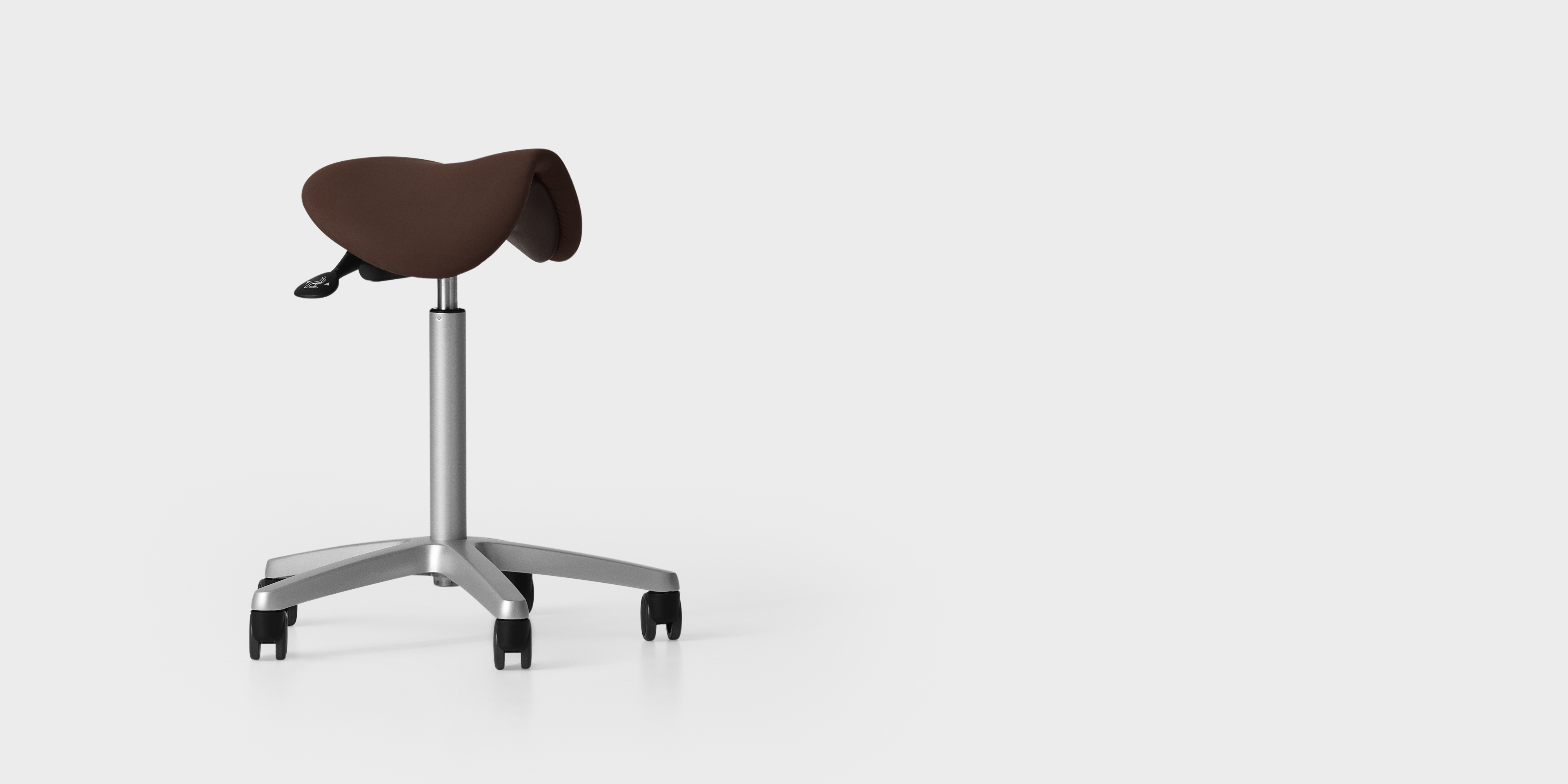
2.29XO SEAT & XO STOOL

2.29.1General

2.29.2XO SEAT

2.29.3XO STOOL

3Infection control and maintenance

3.1General

3.2Infection control and maintenance checklist

3.3Cleaning, disinfection and sterilization methods

3.4Consumables

3.5Detergents and disinfectants

3.6Daily infection control procedure at start up

3.7Infection control procedure after each patient

3.8Daily infection control procedure before shutdown

3.9Instrument hoses and suspensions

3.10Three way syringe & six way syringe (heated) – Luzzani

3.11Micromotor – Bien-Air MX2 & Bien-Air MCX

3.12Air instrument oil separator

3.13Ultrasonic scaler – XO ODONTOSCALER

3.13.1Infection control

3.13.2Check wear of tips regularly

3.13.3Replacement of O-rings

3.14Curing light – XO ODONTOCURE

3.14.1Infection control

3.14.2Testing of effectiveness

3.15Other instruments

3.16Cuspidor bowl and cup holder

3.17Cleaning/exchange of the cuspidor spout

3.18Dashboard, instrument holder and navigator

3.19Handles

3.20Instrument suspension adjustments

3.21Click-on tray holder adjustment

3.22Operating Light

3.23Suction disinfection (manual)

3.24Suction filters

3.25Suction nozzles

3.26Suction hoses

3.27Cuspidor valve – cleaning the coarse filter

3.28Amalgam separator – exchange of amalgam collector vessel

3.29Disinfection of the unit water line (manual)

3.30Checking the unit’s water line quality

3.31XO Water Softener

3.32Replacement of disinfection cartridges

3.33Control of the water disinfection system

3.34Foot control

4Installation

4.1Installation

4.2Installation follow up

5Trouble shooting

5.1System messages

5.2Other possible faults

6Service (authorized service personnel)

6.1General

6.2Preventive service and safety inspection

6.2.1Notification

6.2.2Regular inspection and service

6.2.3Additional inspection and service activities

6.3Technical settings app

6.4Instrument modules

6.5Adjustment of the arm systems

6.6Replacement of operating light source

6.7Ultrasonic scaler – XO ODONTOSCALER

6.8Curing light – XO ODONTOCURE

7Symbols

8Dimensions and technical data

8.1Dimensions and range of motion

8.2Technical specifications

9Legal

9.1Authorized service personnel only

9.2XO CARE General Conditions, Warranty and Service life

9.3Serious incidents

9.4Known contradictions

9.53rd Party instruments and accessories

9.6Product updates

9.7Software version

9.8Applicable standards

9.9Electromagnetic emission

9.10Interference Immunity

9.11Classification

9.12Applied parts

9.13Marking plate

9.14Other labels

9.15Product disposal information


1EXTRAORDINARY DENTISTRY


XO CARE A/S provides treatment solutions that are easy to understand and intuitive to use.

In order to fully benefit from all the extraordinary features of XO FLOW please carefully read these instructions for use:

  • Section 2:Detailed information on how to use the equipment

  • Section 3:Detailed information about infection control and maintenance

  • Section 4:How the XO FLOW unit must be installed?

  • Section 5:XO Flow Trouble shooting guide

  • Section 6:Servicing the Unit by authorized personnel

  • Section 7:List of symbols used

  • Section 8:Dimensions and technical details are listed

  • Section 9:Various legal notices Lists

Visit xo-care.com or contact us at info@xo-care.com for more information.

Best regards

XO CARE A/S


2OPERATION


2.1GENERAL

XO FLOW is a dental treatment unit with a compact floor-mounted unit stand fitted with a patient chair.
The unit has one column with tree balanced arms for instrument bridge, navigator and operating light respectively.
The instrument bridge comprises a dashboard with a touch sensitive display and a graphical user interface for managing and monitoring unit and instruments.
The navigator is a touch sensitive screen offering a variety of dental apps, e.g. selection of user profile with personalized settings, ergonomy guide and remote desktop access to remote computers.

Figure 1 - XO FLOW:
(1) instrument bridge, (2) dashboard, (3) navigator, (4) foot control, (5) patient chair
(6) cuspidor and cup filler (option) and (7) operating light (option)


To avoid injury to persons or material do not use XO FLOW or its accessories if signs of operational, electrical or mechanical defects are found.
Do not use XO FLOW in oxygen-rich environments!
This equipment does not have a gas sealed electronic enclosure and could ignite any flammable or explosive gases in its environment.
Do not simultaneously touch the patient and any external electrical equipment such as PCs, monitors, etc.
Use of other equipment adjacent to or stacked on this equipment should be avoided because it could result in improper operation.
Exercise caution when using the unit in combination with other equipment that can move.
XO FLOW must be used only for prevention and treatment of diseases in the oral cavity of humans.
XO FLOW must only be operated by skilled dental operators.
XO FLOW must be operated in accordance with these instructions for use.
When XO FLOW is used by skilled dental operators no special training is required.
A complete technical description of XO FLOW is available at xo-care.com.


2.2SWITCH THE UNIT ON AND SHUTDOWN

For daily use switch the unit on using the switch (1) in Figure 2 after which a light comes on in the switch.

Figure 2 - Switching the unit on and off:
(1) on switch; (2) mains switch


For shutdown tap on the Dashboard – see Figure 9(3).

When the unit is switched on and when it is shut down with the general disinfection procedures as described in sections (see section 3.6) and (see section 3.8 are automatically invoked


Only use the mains switch – see Figure 2 (2) – for turning off/on all electric power. The mains switch should normally be in the “on” position.

In case of emergency, use the mains switch to turn off the unit.
After switching off the unit wait for at least 30 seconds before the unit is switched on again.


2.3STAND-BY & AUTOMATIC POWER DOWN

When the unit has not been used for 10 minutes it enters into stand-by mode where the Dashboard, Navigator and other energy consuming elements of the unit are shut off.


Exit stand-by mode by activating the foot control, by touching the Dashboard, the Navigator or by lifting an instrument forward.


The stand-by mode function may be configured – see section (see section 2.22.8).


See also section (see section 2.22.8) if you want to enable the automatic power down function.


2.4FOOT CONTROL

2.4.1FUNCTION

Use the foot control to activate the selected instrument and position the patient chair.


Place the foot control close to the unit’s supporting leg and operate it with the right foot when working in operator working positions 9 – 11 o’clock – see Figure 3.

In operator working position 12 o’clock it may be easier to use the left foot (right-handed operator).


Use the hook to position the foot control.


Figure 3 - Optimal position of foot control:
(1) Hook


Figure 4 - Foot control:


As shown in Figure 4 the foot control has:

  • Section 2:A pedal that can be moved to the right (⮕), to the left (⬅) and pressed down (⬇)

  • Section 3:A X button

  • Section 4:A O button

  • Section 5:A joystick that can be moved north (▲), west (◄), south (▼) and east (►)


Table 1 below explains the standard function of the foot control.

Lift chair
Lower chair
Increase backrest inclination
Decrease backrest inclination


X
Programable chair position 1 (when no instrument is activated)
O
Programable chair entry/rinse position (when no instrument is activated)


🠖
Activate the selected instrument
🠔
Activate the selected instrument (micromotors: counter-clockwise)
🠗
N.A.


2.4.2CONFIGURATION
The foot control may be configured in a way different to what is described above, and more functions may be added.

Open the user settings app (see section 2.24.7) on the Navigator and tap to configure the function of the foot control.


Drag and drop unit and chair functions to the desired foot control “button”.

Drag and drop to a foot control “button” that should have no function.


Please note that it is possible to configure the foot control function individually for each of the following unit states
  • All instruments rest
  • Bien-Air MX2 micromotor selected
  • Bien-Air MCX micromotor selected
  • Air instrument selected
  • XO ODONTOSCALER selected
  • XO ODONTOCURE selected


See the actual function of the foot control on the Navigator home screen as shown in Figure 47.


2.5INSTRUMENT BRIDGE

2.5.1GENERAL

It is possible to attach up to 6 instruments (with modules as described in section 6.4) to the instrument bridge.

The instrument bridge is equipped with a detachable instrument holder and a touch sensitive graphical user interface – the Dashboard – for monitoring and controlling unit, patient chair and instruments.


Figure 5 - XO FLOW instrument bridge:
(1) instrument holder (2) Dashboard and (3) handles


To “save space” it is possible to attach a micromotor or an air instrument (turbine) hose to a micromotor module.
Always use the handles to position the instrument bridge.
Never pull the instrument bridge dragging an instrument – this may damage the instrument suspension.


2.5.2INSTRUMENT BRIDGE WORKING POSITION
To obtain easy access to and optimal balancing of the instruments, place the instrument bridge close to the center of the patient’s chest
– with a distance from the tips of the instruments to the oral cavity of 30 cm – see Figure 6.


Figure 6 – Position of the instrument bridge while treating a patient


2.5.3WORKING WITH BALANCED INSTRUMENTS
Grab the instruments from below – thereby avoiding lifting the shoulder – as shown in Figure 7.


Figure 7 – Lifting an instrument forward


All instruments should be in perfect balance when lifted forward
i.e. there should be no dragging from the instrument hose while holding an instrument!
For adjustments of the instrument suspensions (see section 3.20).


2.5.4INSTRUMENT BRIDGE PARKING POSITION
Always place the instrument bridge as shown in Figure 8 when the patient enters or leaves the chair.


Figure 8 – Position of instrument bridge for optimal patient access to the chair


In this position, the patient does not notice the instruments when getting in and out of the chair.
Further the instrument bridge is easily accessible for cleaning and disinfection in this position.


2.6DASHBOARD


The Dashboard is fitted to the front of the instrument bridge and comprises a touch sensitive display

and a graphical user interface as shown in Figure 9.


It is possible to use the graphical user interface of the Dashboard wearing gloves.
Please avoid “air bobbles” in the glove fingertips and make sure that the glass surface of the Dashboard is dry.
It is possible to cover the Dashboard with plastic foil without jeopardizing the function of the touch buttons and sliders.
Please note that it is perfectly possible to monitor and control unit and instruments in spite of the instruments hanging in front of the Dashboard.
Please avoid touching the Dashboard glass front with sharp items such as diamond burs and scaler tips.
Use protective plastic foil to avoid scratches in the glass front.


Figure 9 - DASHBOARD (without instruments and instrument holder):
(1) information bar, (2) Lock dashboard, (3) Shutdown, (4) Patient chair menu, (5) Unit menu
(6) left vertical side menu, (7) right vertical side menu, right vertical side menu,
(8) six instrument displays, (9) six instrument control windows and (10) six instrument selection indicators


2.6.1INFORMATION BAR

Displays time, name of current operator, name of operatory and system message symbols or , if any. See details about system messages in section 2.23.


2.6.2LOCK DASHBOARD AND NAVIGATOR BUTTON

Tap for locking the Dashboard and the Navigator while cleaning and disinfecting the glass surfaces.
Unlock the Dashboard and the Navigator by activating the foot control.


2.6.3PATIENT CHAIR MENU AND UNIT MENU BUTTONS

All patient chair and unit functions may be activated from the Dashboard.
Tap to access the patient chair menu and to access the unit menu
Thereafter tap the button corresponding to the desired function and close the menu by tapping


2.6.4VERTICAL SIDE MENUS

The two vertical side menus can be configured to operate the commonly used unit and patient chair functions.

Open the administration app (see section 2.24.8) on the Navigator and tap to configure the side menus.


Drag and drop unit and chair functions to the desired side menu buttons

Drag and drop to a button that should have no function


Buttons for most used functions should be preferably placed in the lower part of the vertical side menus.


2.6.5INSTRUMENT DISPLAYS

For each instrument the instrument display (see (8) in Figure 9.) shows information related to the specific instrument.


2.6.6INSTRUMENT SELECTION INDICATORS

The instrument selection indicator (see (10) Figure 9.) indicates when an instrument is selected. See details in section 2.7.1.


2.6.7INSTRUMENT CONTROL WINDOWS

For each instrument the instrument control window (see (9) in Figure 9.) is used to control and monitor instrument settings.


The instrument control window can assume four different states:

  • Closed
  • Preset see section 2.8.
  • Workflow see section 2.7.
  • Basic – see section 2.7.


2.7INSTRUMENT CONTROL

2.7.1SELECTING AND ACTIVATING AN INSTRUMENT

While all instruments rest, select an instrument by lifting it forward as described in section 2.5.3.

When an instrument is selected the appropriate instrument selection indicator becomes white (see (11) in Figure 10)
and the instrument control window opens automatically (see (1) in Figure 10).

At any given time maximum one instrument may be selected.

Only the selected instrument may be activated using the foot control.

If a second instrument is lifted forward while an instrument is already featuring as the selected instrument, the selected instrument must be returned to the instrument bridge for the second instrument to automatically become the (new) selected instrument.

Note that the syringe is, however, an instrument which may be used while another instrument is selected – see section 2.15.


The instrument selection described above makes it possible to increase productivity in a safe way as the chairside assistant can prepare an instrument while the operator uses another instrument.


Figure 10 – Basic instrument control:
(1) Instrument control window, (2) button for opening and closing instrument window, (3) speed slider, (4) spray water slider,
(5) spray water selection button (6) spray air selection button, (7) spray air slider, (8) automatic chip blow on/off button,
(9) “tactile” function on/off button, (10) instrument display and (11) instrument selection indicator


Activate the selected instrument with the foot control pedal ( ⮕ or ⬅ ) as shown in Figure 11


Figure 11 - Foot control: Activation of an instrument using the pedal


When activated, the instrument will operate in accordance with the settings – see section 2.7.2. - and the actual speed is shown in the instrument display.


Figure 12 - Instrument display showing the actual micromotor speed


2.7.2MONITORING AND ADJUSTING INSTRUMENT SETTINGS

The instrument control window gives an overview of the instrument settings and is also used to adjust these.

The instrument control window is opened by tapping – See figure 10 (2).


When no preset is active the instrument control window opens automatically when the instrument is lifted forward.


The instrument control window closes automatically when the instrument is laid back on the instrument bridge.


Below it is described how the instrument display is used to display detailed instrument settings.


2.7.3SPEED


When an instrument is selected the display shows the setting of the speed. In the example shown in Figure 10 the speed can be controlled in the range 100 – 40,000 RPM with the foot control pedal.

It is possible to adjust the maximum speed with the “red” slider (3) in Figure 10 and se the new speed range in the display.
Figure 13 shows an example where the maximum speed is reduced to 2,000 RPM making it easy to control the speed precisely in the low RPM area.


Figure 13 - Instrument display: Monitoring and adjustment of maximum speed


2.7.4SPRAY


To monitor the amount of spray water tap the "green" slider (4) in Figure 10

and the see the current amount of spray water in the instrument display.


Adjust the amount of spray water with the “green” slider.


Figure 14 - Instrument display: Monitoring and adjustment of amount of spray water


To switch off the spray water tap – (5) in Figure 10.

When spray water is switched off the "green" slider turns grey and the text "AIR ONLY" is shown in the display – see Figure 15

Switch spray water on again by tapping .


Spray air is monitored and adjusted in the same way as spray water using the "blue" slider.


Spray air is switched off/on with .


Figure 15 – Spray water switched off


In addition to the functions available from the Dashboard

it is possible to configure the foot control with a spray selection function . See section 2.4.


On the one side be sure to work with an amount of spray water and air in the spray that limits the temperature increase at the pulp to 5.5°.
On the other side do not use more spray than necessary to minimize the spray aerosol.
Aerosols and splatter constitutes a potentially life-threatening biological hazard and must be reduced as much as possible.
In case the amount of spray water deviates more than ±20% from the set value a warning will appear in the instrument display.
Please note that some handpieces are designed with “spray mixing compartments” etc. that may cause a drop of water to exit the handpiece head when the motor is stopped.


2.7.5AUTOMATIC CHIP BLOW


When is enabled a short blast of air dries the preparation each time a micromotor stops.


The automatic chip blow function enables a constant clear eyesight of the preparation thereby eliminating changing to/from the syringe.

The automatic chip blow function is enabled/disabled with – (8) in Figure 10 and the setting is displayed in the display.


Figure 16 – Instrument display: Automatic chip blow disabled


2.7.6TACTILE FUNCTION


Use the tactile function to enhance the tactile sense and better feel the difference between drilling in decayed dentine and healthy dentine while excavating.

The tactile function is enabled/disabled with – (9) in Figure 10 and the setting is shown in the display.


2.8INSTRUMENT PRESETS

2.8.1GENERAL

Above in section 2.7, we have described how to manually monitor and control instrument settings.


In this section we describe how to use presets to make it easier to ensure optimal instrument settings for any dental procedure.


A preset is a set of optimal instrument settings for a specific instrument targeted at performing a specific procedure, for example preparation.

Presets are generally named with reference to the specific procedure.


As an example, the micromotor standard preset PREPARATION may be used for preparation of a tooth.

Fitted with a red (1:5) contra-angle handpiece and an appropriate diamond bur the instrument operates

with the following settings when activated with the foot control:

  • "High" speed: 200,000 RPM
  • A "wet" spray with 60 ml/min spray water and spray air adjusted to 60% of maximum
  • Tactile function disabled
  • Automatic chip blow on


Another example is the micromotor standard preset EXCAVATION, that can be used for excavation.

When a blue (1:1) contra-angle handpiece and an appropriate rose head bur is fitted to the instrument,

it will operate with the following settings when activated with the foot control:

  • "Low" speed: 2,000 RPM
  • A spray with only 50 ml/min spray water and spray air adjusted to 50% of maximum
  • Tactile function enabled
  • Automatic chip blow enabled


2.8.2ACTIVATING A PRESET

To select a preset for an instrument tap and a list of available presets appears in the instrument control window.


Figure 17 – Instrument control window - presets

Activate a preset by tapping the appropriate button – for example / PREPARATION – see Figure 18 (1).

The display now instructs the chairside assistant to prepare the instrument in relation to the preset.
In the example in Figure Figure 19. a red contra-angle handpiece and a diamond bur shall be fitted for the preset PREPARATION.

Deactivate the preset by tapping the / PREPARATION button again – or select another preset.


2.8.3SPEED

When the instrument is activated (see section 2.7.1), the speed is shown in the display – see Figure 19 (2).


In presets the speed displayed indicates the speed of the bur.

The micromotor has a maximum speed of 40,000 RPM.

Fitted with a red contra-angle handpiece with a 1:5 gearing the speed of the bur equals 200,000 RPM for example.


In most of the standard presets (see section 2.8.6), the speed is set to be constant.

This means that the only function of the foot control pedal is to start and stop the instrument – not to adjust the speed

In this way it is easier to work with the optimal speed in relation to the task at hand.


Figure 18 – Preset:
(1) Preset activated, (2) instrument activated and (3) Preset adjustment and monitoring


2.8.4TORQUE CONTROL

In relation to some tasks such as for example endo preparations using files it is possible to limit the torque in order to reduce risk of fracturing the file.


The torque limitation can be either specified in % of maximum torque or in Ncm.


If torque limitation is active this is shown in the display.


Figure 19 – Torque limit


If the torque is specified in Ncm, the gear ratio of the contra-angle handpiece and the "efficiency" of the handpiece is considered
Visit xo-care.com for a list of handpiece "efficiencies".


2.8.5MONITORING AND (TEMPORARILY) ADJUSTING A PRESET

To monitor and if necessary (temporarily) adjust a preset tap – see Figure 19 (3)

Follow the instructions listed in section 2.7.


When a preset has been adjusted the word “Adjusted” is shown in the display.
Adjustments are not saved.


2.8.6STANDARD PRESETS
For inspiration XO FLOW is supplied with a number of standard presets for micromotor (section 2.11.3), air instrument (section 2.12.3) and scaler (2.13.4).
The standard presets shall be regarded as a general guide on how to create and use presets.
The person who is professionally responsible of the dental practice shall ensure that presets used at the practice live up to the practice’s professional standards.
The standard presets must not replace the single dental operator’s professional expertise and experience.


2.8.7CONFIGURING PRESETS

Each user may configure his/her own presets.

Open the user settings app on the Navigator to configure presets (see section 2.24.7)


For each type of instrument, tap the associated button to create, modify or delete instrument presets.


Modify a preset by tapping the appropriate button and follow the instruction to the right.

Delete a preset by dragging it to the trash can .


2.9INSTRUMENT WORKFLOWS

When a workflow is activated for a specific instrument and the instrument is lifted forward

the control window opens in workflow mode and the first step is selected


2.10ONE-MOTION-CONTROL

The easiest way to access and manage sliders and buttons of the instrument control

is to use the little finger to operate sliders and buttons while the instrument is lifted forward – see Figure 20

Figure 20 – One-motion-control: Operation of the instrument control window using the little finger


Always use the little finger to control buttons and sliders in the instrument control window.


2.11MICROMOTOR – BIEN-AIR MX2 & BIEN-AIR MCX

2.11.1GENERAL
To avoid risk of cross contamination, only use micromotor handpieces with built-in anti-retraction mechanisms.
Never connect a handpiece to a running micromotor.


2.11.2BASIC FUNCTION


Setup and activate the micromotor as described in section 2.7.


Please note that ⬅ activates the instrument counterclockwise (see Figure 11).


2.11.3PRESETS


See section 2.8 for a description on how the micromotor functions with presets.


Standard presets for micromotors are listed below in Table 2.


Presets may be modified, deleted, or added. See section 2.8.7.


In the standard presets the amount of cooling water and air has been optimized to -

  • on the one hand, to avoid excessive pulp temperature and
  • on the other hand, to minimize spray aerosols for improved infection control and visibility.


Table 2 – Micromotor: Standard presets

# Name Purpose Icon Hand-piece Rotating instrument Max. speed Speed control Tactile function Torque limitation Spray water Spray air Chip blow
            RPM     Ncm ml/min %  
1 Preparation Restorative dentistry:
  • Preparation for a filling
  • Removal of old filling
Crown, bridge, on- and inlay:
  • Preparation
Red 1:5 Diamond 200,000 One-step Disabled Off 60 60 Enabled
2 Excavation Restorative dentistry:
  • Removal of decayed dentine
Blue 1:1 Rose Head 2,000 One-step Enabled Off 50 50 Enabled
3 Finishing Restorative dentistry:
  • Finishing / adjustment of composite / glass ionomer filling
Blue 1:1 Finishing disk / point 25,000 Variable Disabled Off 40 60 Disabled
4 Polishing / cleaning Prophylaxis:
  • Polishing tooth
Restorative dentistry:
  • Cleaning occlusal surface
Blue 1:1 Rubber cup or brush 4,000 One-step Disabled Off Off Off Disabled
5 Pedio Restorative dentistry:
  • Children
Blue 1:1 Rose head 7,000 One-step Disabled Off 20 30 Enabled
6 Acrylic Dentures:
  • Adjustment
Blue 1:1 Technic 40,000 Variable Disabled Off Off Off Disabled


2.12AIR INSTRUMENT

2.12.1GENERAL
To avoid risk of cross contamination, only use air instrument handpieces with built-in anti-retraction mechanisms.


Instruments powered by compressed air (drive air) are called air instruments.


Air instruments may for example be turbine handpieces or air scalers.


For drive air settings please note:


The minimum and the maximum (100%) amount of air flow that can be supplied to an air instrument must be set by authorized service personnel (see section 5) to best match the needs of the dental practice.
Different air instruments (e.g. turbines) operate at different settings.
 
To get the best performance in a scenario where multiple different air instruments are used with one air instrument module, the pressure settings must be adjusted to each type of air instrument.
With XO FLOW, the pressure settings can be adjusted individually on a per preset basis as an advanced option.
Please contact authorized service personnel (see section 5).
 
Please note that some turbine handpieces are designed with “spray mixing compartments” etc.
That may cause a drop of water to exit the handpiece head when the instrument is stopped.


2.12.2BASIC FUNCTION


Setup and activate the air instrument as described in section 2.7 with the following modifications:

  • Replace speed in RPM with drive air level (1 – 10)
  • Tactile function is not available

See Figure 21.


Figure 21 – Instrument control window and display when air instrument is selected


2.12.3PRESETS


See section 2.8) for a description on how the air instrument functions with presets.


Please see Table 3 below for a list of standard presets for the air instrument.


Table 3 – Standard presets: Air instrument

# Name Purpose Icon Hand-piece Rotating instrument drive air Speed / power control Spray / irrigation water Spray air Chip blow
            Level   ml/min %  
1 Preparation
  • Preparation of crown, bridge, on- or inlay
  • Removal of old filling
  • Preparation for a filling
Turbine Diamond 10 One-step 60 60 Enabled
2 Air scaler
  • Scaling
Air scaler none 10 Variable 40 Off Disabled


Presets may be modified, deleted or added. (See section 2.8.7.)


In presets for air scalers spray air must be off.


2.13ULTRASONIC SCALER – XO ODONTOSCALER

2.13.1GENERAL

XO ODONTOSCALER is a piezoceramic ultrasonic scaler for XO units supplied with the parts listed in Table 4:


XO ODONTOSCALER is intended for removal of supragingival calculus and subgingival concretions, endodontics applications and preparation of tooth enamel.
Misuse may damage the scaler and hence cause risks and hazards for patients, operators and third parties.


Table 4 – XO ODONTOSCALER is supplied with

# Item Purpose
1 Handpiece  
1 Universal prophylaxis tip, 1U or 1 US with tip changer Removal of supragingival calculus in all quadrants.
The entire treatment can be carried out without the tedious job of changing tips.
1 Universal prophylaxis tip, 3U or 3US with tip changer Slightly rounded and particularly narrow and short.
Fine scaling in the supragingival region.
Ideal instrument for cleaning the interdental spaces.
1 Periodontology tip, 1P or 1PS with tip changer Removal of concretions in the subgingival region.
Especially suitable for the treatment of deep periodontal pockets.
1 Nozzle cleaner  
2 Optical fibers Spare part
2 O-rings Spare part


Figure 22 – XO ODONTOSCALER:


(1) thread/irrigation outlet, (2) connection for hose,(3) handpiece cap,
(4) optical fiber, (5) optic outlet and (6) nozzle cleaner


Misuse may damage the scaler and hence cause risks and hazards for patients, operators and third parties.
 
XO ODONTOSCALER is available in two different versions indicated with:
  • for W&H tips and tips with EMS compatible thread (for example 1U) – tip changer with grey base
  • for tips with ACTEON® compatible thread (for example 1US) – tip changer with blue base


The thread type ( or ) is indicated on the handpiece as shown in Figure 23, on the tips and on the tip changer.


Figure 23 – XO ODONTOSCALER handpiece:
(1) Mark of tip thread of type


2.13.2EXCHANGE OF TIP

Insert the tip as follows (see Figure 24):

  • Ensure the matching thread system ( or ) at the handpiece, tip changer and tip!
  • Position the tip on the thread of the handpiece (1)
  • Turn the tip changer until a click sound is heard (2)
  • Withdraw the tip changer (3)


Figure 24- Changing the tip


Verify full engagement!
Press the tip with about 1 N (= 100 g) pressure onto a firm object to test the loading capacity of the tip.


Remove the tip as follows:

  • Place the tip changer onto the tip
  • Unscrew the tip with the tip changer


After removal of the tip leave it in the tip changer until cleaning, disinfection and sterilization see section 3.13.)
Ensure that the original shape of the tip is not affected (e.g. if dropped).
The tip must not be bent back into shape or re-sharpened.
Do not activate the instrument while inserting and removing the tip.
Never touch the tip while vibrating.
Insert the tip changer onto the inserted tip of the scaler after every treatment (protection against injury and infection, tip protection).
Do not touch the inside of the tip changer (with tip inserted).
Check for the effect of wear on the tip using the accompanying tip card.
Dispose the tip if it shows visible signs of wear.


2.13.3BASIC FUNCTION

Setup and activate the scaler as described in section 2.7) with the following modifications:

  • Replace speed in RPM with % of maximum amplitude
  • Replace spray water with irrigation water
  • Spray air, tactile function and automatic chip are not available. See picture 25.


The relation between amplitude in % of maximum and power settings used by W&H are as follows:


Amplitude in % of maximum (described in these IFU) Amplitude reference according to W&H
25% 10
50% 20
75% 30
100% 40


Figure 25 – Instrument control window and display when scaler is selected


Always use the tip in parallel with the tooth surface – see Figure 25
Never use the tip perpendicular onto the tooth surface.


Figure 26 – Correct use of the tip


When adjusting the amplitude consult instructions for use issued by the manufacturer of the instrument tips.
Perform a test run each time before use.
Do not hold the scaler close to the eyes!
Do not look directly into the optic outlet
Only touch the tooth surface after the scaler has been activated.
Never operate the scaler freely oscillating without irrigation as this will damage the tips.
For scaling never operate the instrument without irrigation water for more than 30 seconds as this will cause both tip and handpiece to become overheated.
Check the scaler for damage and loose parts each time before use (e.g. tip, handpiece cap).
Do not operate the scaler if it is damaged.
Replace damaged or leaking O-rings immediately.
Do not twist, kink or squeeze the hose (risk of damage).
In the event of operating malfunctions (e.g. vibrations, unusual noise, overheating, coolant supply failure or leakage)
stop the scaler immediately and contact authorized service personnel – see section 9.1.)


If XO ODONTOSCALER is used for endo treatments, please observe:


If the instrument is operated without irrigation the maximum operation time is limited to two minutes.
After two minutes of operation without irrigation a warning will appear in the instrument display until the handpiece and tip have cooled down.


2.13.4PRESETS

See section 2.8) for a description on how the scaler functions with presets.


A list of standard presets for XO ODONTOSCALER is listed in Table 5.


Table 5 – Standard presets: Air instrument

# Name Purpose Icon Handpiece Tip Maximum amplitude Power control Irrigation water
            %   ml/min
1 Coarse scaling For coarse depuration of supragingival plaque. 1U 100 Variable 40
2 Fine depuration For fine depuration of supragingival plaque, especially suitable for interdental cleaning. 3U 80 Variable 40
3 Perio Removal of subgingival deposits, especially suitable for deep periodontal pockets. 1P 50 Variable 30
4 Cleaning of scaler Cleaning after use.   20 One Step 60


Presets may be modified, deleted or added. (See section 2.8.7.)


When working with the PERIO preset please observe:


With periodontal tips, the instrument is suitable for the removal of concretions in the subgingival region, but not for applications which demand sterile conditions.
Be careful to exceed the preset power in the standard presets when carrying out periodontal treatments on hypersensitive patients to guarantee optimum pain-free treatment.


2.14CURING LIGHT – XO ODONTOCURE

2.14.1GENERAL
The intended use of XO ODONTOCURE is polymerization of light cure resin-based composites used for fillings in human teeth.


XO ODONTOCURE is a "multipeak" type curing light, meaning the emitted light has two peak values making it suitable for filling composites containing several initiators.

See section 8.2 for further technical specifications.


Table 6 – XO ODONTOCURE is supplied with

Pcs. Item Purpose
1 Fiber glass rod  
1 Light Shield To avoid eye damage while curing of anterior teeth
100 Sleeves To avoid cross infection
3 Testing devices Measuring curing effectiveness


2.14.2BASIC FUNCTION


Select the instrument and see 1) the preset exposure time and 2) the radiant exitance in the instrument display as shown in Figure 27.


The instrument control window contains sliders for adjusting instrument data:

  • Use the “red” slider above the icon to adjust the exposure time and see the new exposure time in the instrument display
  • Use the “yellow” slider above the icon to adjust the radiant exitance and see the new radiant exitance value in the instrument display


Start the curing cycle with 🠖 or 🠔 (see Figure 11).


See the remaining exposure time in the instrument display.


Figure 27 – Instrument control window and display when XO ODONTOCURE is selected


Stop the curing cycle if necessary with 🠖 or 🠔 by deselecting the instrument.


When the curing cycle has ended, a acoustic signal is emitted


For the best results, the distal end of the light rod should be held perpendicular and as close as possible to the tooth surface.
XO ODONTOCURE emits blue and ultraviolet light in the 385 – 515 nm range at an intensity that requires protection of the eyes.
Direct exposure to the light may cause permanent eye damage. Therefore never look directly into the light or direct it at the eyes of others!
Protect the eyes of the dental operators and the patient with light shield and protective eyewear that removes light in the abovementioned wavelengths.
The high radiant exitance generated by XO ODONTOCURE is accompanied by heat generation in the exposed tooth tissue!
Make sure to keep tooth tissue temperature increase below 5.5°.
If the warning “XO ODONTOCURE handpiece too hot” is displayed in the instrument display the instrument is turned off.
When the warning is no longer displayed the instrument is ready for re-activation.


While curing of anterior teeth use the light shield:


Figure 28 Light Shield


2.15THREE WAY SYRINGE & SIX WAY SYRINGE (HEATED) – LUZZANI

Select water, air or spray and adjust the amount of water and air using the two buttons on the syringe handpiece:

    • Water by activating the button button
    • Water by activating the button

  • Spray by activating both buttons simultaneously


To minimize the spray aerosol do not use more air and water spray than necessary.
Aerosols and splatter constitutes a potentially life-threatening biological hazard and must be reduced as much as possible.


Enable/disable the heating element (six way syringe only) for water and air by tapping in the instrument control window – see details in Figure 29.

Figure 29 – Instrument control window: Six way syringe


The syringe may be used while another instrument is selected and activated – see section 2.7.1.


2.16CLICK-ON TRAY HOLDERS

The optimal place for hand-instruments etc. is near the patient’s temple – see Figure 30 - where both operators can reach the instruments in good postures.


Figure 30 – Cabinet mounted tray holder near the patient’s temple


As an alternative or as a supplement to this, XO FLOW may be configured with one or two tray holders fitted under the instrument bridge – see Figure 31.


Figure 31 – Click-on tray holders


Place the tray in the tray holder just by pushing the tray sideways into the holder (see Figure 32).
In this way, instruments and other objects will remain in place while the tray is inserted into the holder.


Figure 32 – Positioning the tray in the holder


Tilt the tray to remove it (1) as shown in Figure 33 or release the tray holder mechanism by lifting the outer ring (2) in Figure 33.


Figure 33 – Removing the tray from the holder:
1) by tilting the tray or
(2) by lifting the outer ring of the tray holder mechanism


XO tray holders are designed for use with norm trays with a height of 17 mm ± 0.5 mm.


Maximum load on one tray holder must not exceed 0.75 kgs.
Exceeding this limit may compromise the balance of the instrument bridge and could cause the bridge suspension arm to fail thereby exposing the patient to a health hazard.


2.17PATIENT CHAIR

The patient chair is mounted on the side of the unit providing maximum legroom for the operator and the chairside assistant.
The chair has a backrest with integrated armrests and a double hinged neck rest.

XO FLOW is designed with over-the-patient delivery of instruments for working primarily on supine patients, that allows the operators to see all tooth surfaces in good working postures.

XO FLOW is intended to be used primarily with supine patients!


The chair height and the backrest inclination can be increased/decreased by use of either the foot control or the vertical side menus on the Dashboard.
Furthermore, two programmable chair positions (1 and 2) and a programmable entry/rinse position may be configured for the preference of each individual operator.


2.17.1FOOT CONTROL OF PATIENT CHAIR

Use the foot control to position the patient chair as described in section 2.4.


2.17.2DASHBOARD CONTROL OF PATIENT CHAIR

Alternatively, when using the Dashboard (see Figure 9.) for operating the patient chair a wider selection of choices is given:


a)the configurable buttons in the vertical side menus (if configured for chair functions)

b)or activating followed by:


Programmable chair position 1

Programmable chair position 2

Programmable chair entry/rinse position

Previous position (the last “still” position prior to the present)

Lift chair

Lower chair

Increase backrest inclination

Decrease backrest inclination


Close the chair menu by tapping .


For safety reasons , , and do not function while an instrument is activated.


2.17.3CONFIGURING THE PROGRAMMABLE PATIENT CHAIR POSITIONS

Open the user settings app on the Navigator and tap .


Position the chair as desired using the foot control or Dashboard vertical side menu buttons.

Tap , and or to update the respective programmable chair position. See details in section 2.24.7.


2.17.4CONFIGURING DASHBOARD CONTROL OF PATIENT CHAIR

Open the user settings app on the Navigator and tap to configure the Dashboard’s vertical side menus with patient chair buttons.


See details in section 2.24.7.


2.17.5NECK REST

The patient chair is equipped with an adjustable neck rest supporting the patient’s neck and head.


To obtain the best patient experience please follow these instructions while the patient is moving towards a programmable chair position:

  • Activate the chair towards a programmable chair position
  • While the chair moves towards the programmable chair position use the left hand and gently push the neck rest to provide optimal support of the patient’s head – see Figure 34 (1)
  • When in the programable chair position, adjust the angular position of the neck rest using the release handle (2)

Figure 34 – Neck rest:
(1) push the neck rest while the chair moves and
(2) release the handle


2.17.6CHILD CUSHION

For treatment of children, a child cushion is available.

Figure 35 – Child cushion


2.17.7POSITIONING THE PATIENT

The patient chair neck rest makes it possible to position the patient’s head in six different positions (see Figure 36).
This combined with the flexibility of working in positions between 9 and 12 o’clock (see Figure 37), provides you with the best possible view of each tooth surface without bending or straining your neck, spine or upper body.

Figure 36 – Three lower jaw and three upper jaw patient positions


2.17.8OPERATORS’ SITTING POSITIONS

With the patient placed in the chair in the supine position it is possible to work in positions between 9 o’clock to 12 o’clock (see Figure 37) and obtain the best possible vision while maintaining a healthy sitting position (see section 2.26).

Figure 37 – Four operator’s positions


2.17.9PATIENT CHAIR SAFETY
The patient chair has been designed with an automatic collision detection function meaning that the legs of the operators or anything else cannot be trapped under the chair when moving downwards.


The patient chair is equipped with a function stop:
In case of a risk of health hazard, the operator must interrupt all automatic chair movements immediately by touching any button on the foot control or by lifting an instrument forward.


The patient chair is dimensioned to carry a patient with a weight of up to 150 kg!
Exceeding the maximum allowed weight will compromise the structural stability of the unit as well the patient chair and could result to health hazard.


2.18OPERATING LIGHT

2.18.1POSITION THE LIGHT
Position the light 70 cm from the patient’s oral cavity and set the light so that the direction of the light is parallel to your viewing direction.
- See Figure 38.

This position of the light gives the best illumination of the work area and it prevents the instrument suspensions from touching the light.

Figure 38 – Correct position and distance of operating light


2.18.2AUTOMATIC FUNCTIONS

The light automatically switches on when the patient chair reaches the programmable chair positions 1, 2 or previous position.

The light automatically switches off when the patient chair is moved towards a programmable position, the entry position or previous position.


2.18.3DASHBOARD CONTROL OF OPERATING LIGHT

Alternatively, the operating light may be operated from the Dashboard Figure 9, using:

    1. the configurable buttons in the vertical side menus (if configured for operating light functions)
    2. or opening the light menu with followed by:

for switching the light on/off

for adjusting the light intensity


Close the light menu by tapping .

Please note that using the operating light’s maximum light intensity over long time may have an adverse effect on the operator’s eyes.
The use of maximum light intensity is recommended only for operators with reduced eye sensitivity.
Please note that the operating light does not have a setting that is compatible with light cure resin-based composites.


2.18.4CONFIGURING THE OPERATING LIGHT SETTINGS

Open the user settings app on the Navigator and tap to configure the operating light.


See details in section 2.24.7.


2.18.5CONFIGURING DASHBOARD CONTROL OF OPERATING LIGHT

Open the user settings app on the Navigator and tap to configure the Dashboard’s vertical side menus with patient chair buttons.


See details in section 2.24.7.


2.19SUCTION

The unit is equipped with a high volume and a saliva suction.


2.19.1AUTOMATIC START/STOP OF THE SUCTION

The high volume and the saliva suction hoses start automatically when lifted from the holder and stop when repositioned.


2.19.2DASHBOARD CONTROL OF SUCTION

The suction may be operated from the Dashboard Figure 9.:

  • Using the configurable buttons ( and/or ) in the vertical side menus
  • Or opening the unit menu with followed by tapping or ,


Where:

switches the high-volume suction on/off (can be used to remove excess filling materials etc. while the hose is placed in the suction holder)

switches the saliva suction on/off.


2.19.3CONFIGURING DASHBOARD CONTROL OF SUCTION

Open the user settings app on the Navigator and tap to configure the Dashboard’s vertical side menus with patient chair buttons.


See details in section 2.24.7.


2.19.4RIGHT-HANDED OPERATOR

Position the suction hose holder in the duo position when working four handed (see (1) Figure 39)

and in the solo position (see (2) Figure 39) when working two handed.


See details in section 2.24.7.

If the unit is permanently used by a right-handed operator, the short suction hoses version (175 cm) should be used – see Table 11.


2.19.5LEFT-HANDED OPERATOR

Position the suction hose holder in the duo position when working four handed (see (4) Figure 39) and in the solo position (see (3) Figure 39) when working two handed.

Figure 39 – Ambidex suction hose holder:
(1) Right-handed/duo position, (2) Right-handed/solo position
(3) Left-handed/solo position or (4) Left-handed/duo position


If the unit is (permanently or part time) used by a left-handed operator,the long suction hoses version (260 cm) should be used – see Table 11.

When using the long suction hoses it is necessary to attach the hoses to the suction arm supplied Velcro tape as shown in Figure 40.

Figure 40 – Attachment of suction hoses


2.19.6SUCTION HANDLING

When working four-handed the chairside assistant grabs the high-volume suction with the right hand as shown in Figure 41.

Figure 41 – Chairside assistant grabs the high-volume suction hose with the right hand

When working solo the operator grabs the high-volume suction hose as shown in Figure 42.

Figure 42 – Solo working operator grabs the high-volume suction hose with the left hand


If necessary, relieve the weight of the suction hoses by pressing it into the slot in the lower part of the suction hose holder as shown in Figure 43.

Figure 43 – Relieving the suction hose

To minimize the spread of aerosols in the treatment room, an efficient suction technique using the high-volume suction tip adjacent to the aerosol-generating instrument is necessary.


After use just let go of the hoses and they will automatically reposition in the suction hose holder.

Figure 44 – Automatic repositioning of the suction hoses


2.19.7WET / DRY SUCTION SYSTEM

XO FLOW may be fitted with a cuspidor valve and connected to a wet suction system – see details in section 3.27.

Or alternatively the unit may be fitted with an amalgam separator and connected to a dry suction system – se details in section 3.28.


2.20CUSPIDOR AND CUP FILLER

If the unit is supplied with cuspidor and cup filler please read below, else see section 2.19.


2.20.1AUTOMATIC FUNCTION

The cuspidor flush starts automatically after the cup filler has been activated and when the patient chair reaches the preset chair entry/rinse position.


2.20.2MANUAL CONTROL CUSPIDOR AND CUP FILLER

Start the cuspidor flush manually with a short activation of (see (1) in Figure 45.


The rinsing stops automatically after the preset rinsing time.

Abort the cuspidor rinse with while rinsing.

If is touched for more than half a second, the cuspidor flushes only while the button is activated.


Start the cup filler manually by tapping (see (2) in Figure 45).


The glass fills with the pre-configured amount of water.

Abort the cup filler with while filling.

If is activated for more than half a second, water fills the cup only while the button is activated.

Figure 45 – Manual start of cuspidor (1), cup filler (2) and (3) (small) patient tray


2.20.3DASHBOARD CONTROL OF CUSPIDOR AND CUP FILLER

Alternatively, the cuspidor and the cup filler may be operated from the Dashboard (see Figure 9), using:

a)The configurable buttons in the vertical side menus (if configured for cuspidor and/or cup filler functions)

b)Or opening the unit menu with followed by:


For controlling the cuspidor flush:

Start the cuspidor flush with a short activation of .


The rinsing stops automatically after the preset rinsing time.

Abort the cuspidor rinse with while rinsing.

If is touched for more than half a second, the cuspidor flushes while the button is activated.


For controlling the cup filler:

Start the cup filler manually by tapping .


The glass fills with the pre-configured amount of water.

Abort the cup filler with while filling.

If is activated for more than half a second, water fills the cup while the button is activated.


Close the unit menu by tapping .


2.20.4CONFIGURING CONTROL OF CUSPIDOR AND CUP FILLER

Open the user settings app on the Navigator and tap to configure the Dashboard’s vertical side menus with cuspidor and cup filler buttons.

See details in section 2.24.7.


It is possible to configure the cuspidor’s preset rinsing time and the amount of water to the cup filler with the app.

See details in section 2.24.8.


2.20.5PATIENT TRAY

The patient tray (see (3) in Figure 45) can be used to place the patient’s glasses or other personal belonging during the treatment.


2.21UNIT WITHOUT CUSPIDOR AND CUP FILLER

If the unit is not fitted with cuspidor and cup filler a large patient tray (see Figure 46) is fitted to the drain pipe also used during disinfection of the unit’s water line as described in section 3.8.

The patient tray can be used to place the patient’s glasses or other personal belonging during the treatment.

Figure 46 – Patient tray (large) for unit without cuspidor


2.22CALL ASSISTANT


2.22.1DASHBOARD CONTROL OF ASSISTANT CALL

The assistant call may be operated from the Dashboard (see Figure 9), using:

Alternatively, the cuspidor and the cup filler may be operated from the Dashboard (see Figure 9), using:

a)The configurable buttons in the vertical side menus (if configured for assistant call )

b)Or opening the unit menu with followed by:


for activating assistant call (a relay contact that may be connected to a bell or other external signaling device).

Start the cuspidor flush with a short activation of .


Close the unit menu by tapping .


2.22.2CONFIGURING DASHBOARD CONTROL OF ASSISTANT CALL

Open the user settings app on the Navigator and tap to configure the Dashboard’s vertical side menus with cuspidor and cup filler buttons.

See details in section 2.24.7.


2.22.3CONFIGURING FOOT CONTROL OF ASSISTANT CALL

Open the user settings app on the Navigator and tap to configure the foot control with assistant call .

See details in section 2.24.7.


2.23NAVIGATOR

The Navigator is a touch sensitive screen primarily intended for activating and displaying apps related to the XO FLOW unit and other devices and software systems connected in the network.

Figure 47 – Navigator home screen:
(1) information bar, (2) apps, (3) system messages,
(4) foot control guide and (5) home button


When the unit is switched on, the Navigator displays the home screen – see Figure 47.


It is possible to use the graphical user interface of the Navigator wearing gloves.
Please avoid “air bobbles” in the glove fingertips and make sure that the glass surface of the Dashboard is dry.
It is possible to cover the Navigator with plastic foil without jeopardizing the function of the touch buttons and sliders.


The Navigator is not intended for diagnostic use but may be used to display x-ray images for informational purposes.


2.23.1INFORMATION BAR

Displays time, name of current operator and name of operatory.


2.23.2SYSTEM MESSAGES

The most recent messages are stated in headlines on the top right corner of the Navigator home screen – see Figure 47 (3).

See details about system messages in section 2.25.


2.23.3APPS

Tap an app to activate it.

When tapping, for example, the user settings app the Navigator will show the user settings screen as shown below.

Figure 48 – User settings app active

Return to the home screen by tapping the home button (5) in Figure 47.

See details about apps in section 2.24.


2.23.4FOOT CONTROL GUIDE

The foot control guide displays the current functioning of the foot control.

This feature is included in the Navigator as the foot control is context sensitive and as it is possible to configure the function of the foot control.

See details about system messages in section 2.4.


2.23.5HOME BUTTON

Activate the home button (5) in Figure 47 to return to the home screen.


2.23.6POSITIONING

For use by the operator and/or the chairside assistant the Navigator may be positioned on both sides of the instrument bridge – see Figure 49 (1) and (2).

For the purpose of showing screen images to the patient, the Navigator may also be positioned above the patient’s head – see Figure 49 (3).

Further it is possible to tilt the Navigator to the desk position as shown in Figure 49 (4).

see also section 2.24.11.

Figure 49 – Positioning the Navigator:
(1) viewing position at the chairside assistant’s side; (2) viewing position at the operator’s side,
(3) patient viewing position above the patient or (4) desk position


2.24APPS

Some of the most used apps available on the Navigator home screen are described below.


2.24.1SELECT USER APP

Tap to select a new user.


When a user profile has been selected a number of personalized features become available, such as:

  • Programmable patient chair positions
  • Operating light intensity and features
  • Cup filler and cuspidor settings
  • Foot control function
  • Instrument presets


User settings can be modified using the user settings app – see section 2.24.7.


When the unit is switched on (or returns from stand-by mode), the last user will automatically be set as the current user.


2.24.2REMOTE DESKTOP APP

The remote desktop app gives access to monitor and manage computer programs running at computers attached to the network.


2.24.3HELP APP

These instructions for use and various instruction videos are available online. Tap .

Use the search function to navigate the instructions for use.


2.24.4PRE-TREATMENT CHECKLIST APP

To get the maximum benefit of the XO FLOW unit, tap to see how to position/use:

Use the search function to navigate the instructions for use.

  • Patient and patient chair
  • Operators
  • Instrument bridge
  • Dashboard
  • Instruments
  • Suction
  • Operating light
  • Navigator

in order to perform EXTRAORDINARY DENTISTRY.


2.24.5ASEPSIS APP

The asepsis app is used to manually control cleaning and infection control functions as described in sections 3.23 and 3.29.


2.24.6STATUS APP

The status app gives access to information such as:

  • List of active notifications and warnings
  • Date of next preventive service and inspection
  • Serial number of the unit


2.24.7USER SETTINGS APP

Open the user settings app on the Navigator to configure the following settings related to the user who is currently active:

  • Programable patient chair positions and functions – see section 2.17
  • Operating light functions – see section 2.18
  • Cuspidor and cup filler functions – see section 2.20
  • Foot control function – see section 2.18
  • Instrument presets for each type of instrument – see section 2.8


Please note that this app always relates to the currently active user profile.
A user may modify her/his own settings, but not the settings of other users.


2.24.8ADMINISTRATION APP

This app is used to administer users and various technical settings:

    • Enable/disable and adjust stand-by and automatic shutdown – see section 2.3


  • User management (add and delete users)
  • Configuration of Dashboard vertical side menus
  • Name of unit/treatment room
  • Remote desktop
  • Sound volume
  • Amount of water supplied by the cup filler
  • Duration of cuspidor flush


Access to the administration app is protected by a pin code (= last four digits in the unit’s serial number).

Figure – Administration app


2.24.9TECHNICAL SETTINGS APP

is accessible for authorized service personnel only. See section 6.3


2.24.10FUTURE APPS

XO CARE A/S is committed to develop additional apps to become available with software updates.


2.24.11VIRTUAL KEYBOARD

For apps that require writing – for example the name of a preset – a virtual keyboard appears in the lower part of the Navigator app screen image when necessary.

see the example in Figure 50.

Figure 50 – Navigator: Virtual keyboard

Please position the Navigator in the desk position when writing – see Figure 49 (4).


2.25NETWORK CONNECTION


2.26SYSTEM MESSAGES

The unit has the possibility of issuing system messages.

If a system message is pending a symbol will appear on the Dashboard information bar.

Messages may be either notifications indicated by concerning e.g. maintenance, or warnings indicated by .

Messages can be read on the Navigator. The most recent messages are stated in headlines on the top right corner of the Navigator home screen – see Figure 47 (3).

To read all messages in full go to the status app – see section 2.24.6.

Address the matter described in the message. If no action is taken, the message will remain on the screen.

In case of an urgent event, the normal function of the unit will be suspended, and a message will be shown on the Dashboard. Please follow the instructions given on the Dashboard.


2.27ACCESSORIES

The following accessories are available for XO FLOW.


Table 7 – XO FLOW: Accessories

REF. DESCRIPTION
FL-100 Syringe module, supplied without syringe.
FL-101 Luzzani three-way syringe with hose, for syringe module FL-100.
FL-102 Luzzani six-way syringe (heated) with hose, for syringe module FL-100.
FL-110 Air instrument (turbine) module, supplied without hose.
FL-111 Micromotor and air instrument (turbine) module, supplied without hose and micromotor.
FL-112 Air instrument (turbine) hose with connector (ISO 9168 type 3b), for modules FL-110 and FL-111.
FL-115 Bien-Air MX2 micromotor with hose (rotation + 200°), for module FL-111.
FL-117 Bien-Air MCX micromotor with hose (rotation + 200°), for module FL-111.
FL-131 XO ODONTOSCALER module, supplied without scaler.
FL-133 XO ODONTOSCALER LED piezo scaler with hose, handpiece and 3 tips (for W&H tips and tips with EMS compatible thread), for module FL-131
FL-135 XO ODONTOSCALER LED piezo scaler with hose, handpiece and 3 tips (for tips with ACTEON (Satelec) compatible thread), for module FL-131
FL-140 XO ODONTOCURE curing light module.
FL-141 XO ODONTOCURE curing light with hose, hand-piece and light rod, for light curing module FL-140.
FL-190 "Blind" module.
FL-230 Suction system for two hoses with XO Ambidex holder and suction disinfection (suction hoses and suction disinfection/clean cartridges not included)
AR-124 2 suction hoses, L= 175 cm (for XO Ambidex holder, right-handed operator)
AR-127 2 suction hoses, L= 260 cm (for XO Ambidex holder, right- and left-handed operators)
FL-235 Dry suction interface (CAS 1 Combi-Separator)
FL-236 Wet suction interface (cuspidor valve)
FL-270 XO Operating light
XO-813 Child cushion – Grey skai
FL-240 Unit supplied without cuspidor and cup filler
FL-250 Tray holder mounted under instrument bridge (maximum two tray holders may be fitted).
FL-262 Quick connection air
FL-263 Quick connection procedural water
XO-492 Installation plate for XO unit in silver (cannot be used on units with adaptor for intraoral X-ray unit)
FL-300 X-ray adaptor – Ø 24,1 mm (not possible with XO-492)
FL-301 X-ray adaptor – Ø 25,1 mm (not possible with XO-492)
FL-302 X-ray adapter – Ø 30,1 mm (not possible with XO-492)
FL-303 X-ray adaptor – Ø 32,1 mm (not possible with XO-492)
FL-304 X-ray adaptor – Ø 35,1 mm (not possible with XO-492)


2.28FOUR-HANDED AND SOLO WORK

XO FLOW is equally suited for four-handed operation (Figure 51) and two-handed operation (Figure 52).

Figure 51 – Four-handed operation


Figure 52 – Two-handed operation


2.29XO SEAT & XO STOOL

2.29.1General

We recommend that practitioners sit in an upright, balanced position with an angle between thighs and upper body of about 120° – see Figure 53.

In order to remain healthy it is extremely important to maintain a healthy sitting position by adjusting the height and seat angle of the operator’s stool as described in this section!


XO SEAT and XO STOOL are available in two sizes: 1) for operators below 180 cm of height and 2) for operators who are taller.

If the XO SEAT/XO STOOL is too low or too high, it is possible to replace the gas spring with a shorter or longer version.


If the height difference between the operator and the chairside assistant is more than 10 cm, a foot-ring may be fitted.

Figure 53 – Upright, balanced, sitting position


2.29.2XO SEAT

Adjust the seat height using the left handle as shown in Figure 54.

Figure 54 – Upright, balanced, sitting position


Adjust the seat angle with the right handle as shown in Figure 55.

Figure 55 – Adjusting the seat angle


2.29.3XO STOOL

Adjust the seat height as shown in Figure 56 and the seat angle as shown in Figure 57.

Figure 56 – Adjusting the seat height


Figure 57 – Adjusting the seat angle


Adjust the backrest as shown in Figure 58 and Figure 59.

Figure 58 – Adjusting the backrest angle


Figure 59 – Adjusting the backrest height


3INFECTION CONTROL AND MAINTENANCE


3.1GENERAL

  • The sterilization package must meet the applicable standards in respect of quality and use and must be suitable for the sterilization method
  • The sterilization package must be large enough for the sterilization goods
  • The filled sterilization package must not be under tension
All infection control, maintenance activities and adjustments described in this section can be done by the user provided that these provisions are strictly followed.
Wear protective clothing, safety glasses, face mask and gloves.
Use only original consumables, accessories and spare parts provided by XO CARE A/S.
Before using the XO FLOW unit for the first time it must be cleaned, disinfected and/or sterilized as described below.
For any instruments not manufactured by XO CARE A/S, always follow the cleaning, disinfection and sterilization instructions included by the manufacturer!
Before using a thermodisinfector and an autoclave read the instructions for use for the devices and be aware of the warnings provided by the manufacturers.
Pack items to be sterilized in sterilization packages that meet the following requirements:
Store sterile goods dust-free and dry.


Please note that autoclaving and thermo-disinfection processes wear down the materials and may cause change of color and/or shorten the lifetime.
The shelf life of the sterile goods depends on the storage conditions and type of packaging.


  • The safety of operators and patients may be compromised,
  • The service life of the unit expires and
  • XO CARE A/S has no responsibility for the product’s correct functioning and safety.
If the described cleaning, disinfection and sterilization methods are not followed carefully:


Danger of electric shock!
Do not attempt to open the unit other than described in this section.


3.2INFECTION CONTROL AND MAINTENANCE CHECKLIST

Below is a summary of suggested infection control and maintenance procedures.

Table 8 – Infection control and maintenance routines

When: What: Ref.:
Every morning Start the unit and perform the general daily infection control procedure. 3.6
After each patient Clean, disinfect unit and patient chair and clean, disinfect, sterilize the instruments. 3
Every evening Shutdown the unit and perform the general daily cleaning, disinfection and sterilization procedure. 3.8
Every second week Check the unit’s water line quality 3.30
Every month Control the water disinfection system. 3.33
Clean the coarse filter in the cuspidor valve, if installed. 3.27
Measure curing depth of XO ODONTOCURE. 3.14.2
Every 12 months Replace suction hoses and filters. 2.27
Every 24 months Preventive service and safety inspection. 6.2


3.3CLEANING, DISINFECTION AND STERILIZATION METHODS

Table 9 below describes relevant cleaning, disinfection and sterilization methods.

Table 9 – Cleaning, disinfection and sterilization definitions

Procedure Symbols Purpose Methods
Manual cleaning N.A. Removal of visible blemishes spots, stains etc.
  • Physical/chemical use of a mild detergent (e.g. liquid dish soap) – will not significantly reduce the number of pathogens.
Chemical disinfection N.A. Significantly reduce the number of pathogenic microorganisms
  • Application of chemical disinfectants to surfaces.
Machine cleaning and disinfection Significantly reduce the number of pathogenic microorganisms
  • Thermal disinfection at 93°C/194°F, 5 minutes.
  • XO CARE recommends thermal disinfection in a washer-disinfector according to ISO 15883-1 (e.g. Miele PG 8581).
Sterilization Elimination/destruction of all living pathogenic microorganisms
  • Steam sterilization in an autoclave at 134°C/273°F, 3 minutes.
  • The sterilization process shall be validated and routinely controlled according to EN ISO 17665.
  • XO CARE recommends sterilization in a steam sterilizer (autoclave) according to EN 13060, Type B (e.g. W&H Lisa 517 sterilizer).


Clean, disinfect and sterilize XO FLOW as described below in Table 10.

Table 10 – Cleaning, disinfection and sterilization methods / List of detachable parts

Product Ref.: Section Cleaning Chemical disinfection Thermo-disinfection Sterilization
All surfaces of the unit and patient chair N.A. 3.5 Mild detergent with a twisted lint-free cloth. XO Gentle Disinfection N.A. N.A.
Dashboard and Navigator glass fronts N.A. 3.5 Mild detergent with a twisted lint-free cloth. XO Intensive Disinfection N.A. N.A.
3.18
XO Comfort tissue N.A. 3.5 Dry or moisturized soft lint-free cloth. XO Fabric Makeup. XO Gentle Disinfection N.A. N.A.
Instrument holder AR-193 3.5 Mild detergent with a twisted lint-free cloth. XO Intensive Disinfection N.A. N.A.
3.18
Instrument holder cover MN-621 3.5 Mild detergent with a twisted lint-free cloth. XO Intensive Disinfection 250 cycles N.A.
3.18
Handles AP-732 3.19 Mild detergent with a twisted lint-free cloth. XO Intensive Disinfection 250 cycles N.A.
Instrument suspensions AR-200 3.9 Mild detergent with a twisted lint-free cloth. XO Gentle Disinfection 250 cycles N.A.
Tip for syringe SD-214 3.10   XO Intensive Disinfection 250 cycles 250 cycles
Tip retainer SD-516 3.10   XO Intensive Disinfection 250 cycles 250 cycles
Handpiece cover for six-way syringe SD-510 3.10   XO Intensive Disinfection 250 cycles 250 cycles
Instrument hose six-way syringe FS-643 3.9 Mild detergent with a twisted lint-free cloth. XO Intensive Disinfection N.A. N.A.
Micromotor, Bien-Air, MX2 HT-256 3.11 Mild detergent with a twisted lint-free cloth. XO Intensive Disinfection N.A. 500 cycles
Instrument hose Micromotor, Bien-Air, MX2 FS-653 3.9 Mild detergent with a twisted lint-free cloth. XO Intensive Disinfection N.A. N.A.
Instrument hose air instrument FS-645 3.9 Mild detergent with a twisted lint-free cloth. XO Intensive Disinfection N.A. N.A.
XO ODONTOSCALER handpiece HT-259 3.13   XO Intensive Disinfection N.A. 500 cycles
HT-260
XO ODONTOSCALER tips
(REF incl. tip changer)
  • 1U, UH-402
  • 3U, UH-403
  • 1P, UH-404
3.13   XO Intensive Disinfection 500 cycles 500 cycles
  • 1US, UH-405
  • 3US, UH-406
  • 1PS, UH-407
XO ODONTOSCALER tip changer N.A. 3.9   XO Intensive Disinfection 250 cycles 250 cycles
XO ODONTOSCALER nozzle cleaner UH-452 3.13 Ultrasonic bath XO Intensive Disinfection 500 cycles N.A.
XO ODONTOSCALER optical outlet UH-451 3.13 Mild detergent with a twisted lint-free cloth. N.A. N.A. N.A.
XO ODONTOSCALER handpiece cap UH-450 3.13   XO Intensive Disinfection 500 cycles 500 cycles
XO ODONTOSCALER optical fiber UH-453 3.13 Mild detergent with a twisted lint-free cloth. N.A. 500 cycles 500 cycles
Instrument hose XO ODONTOSCALER FS-721 3.9 Mild detergent with a twisted lint-free cloth. XO Intensive Disinfection N.A. N.A.
XO ODONTOCURE fiber glass rod AP-915 3.14 Mild detergent with a twisted lint-free cloth. XO Intensive Disinfection 250 cycles 250 cycles
XO ODONTOCURE handpiece FS-677 3.14 Mild detergent with a twisted lint-free cloth. XO Intensive Disinfection N.A. N.A.
XO ODONTOCURE light shield AP-916 3.14 Mild detergent with a twisted lint-free cloth. XO Intensive Disinfection N.A. N.A.
Instrument hose XO ODONTOCURE N.A. 3.9 Mild detergent with a twisted lint-free cloth. XO Intensive Disinfection N.A. N.A.
XO Operating light protection screen AO-639 3.22 Dry soft lint-free cloth. XO Gentle Disinfection N.A. N.A.
Cuspidor bowl MG-395 3.16 Clean under warm running tap water using a brush. XO Intensive Disinfection 250 cycles N.A.
Protection disk for cuspidor bowl AP-764 3.16 Clean under warm running tap water using a brush. XO Gentle Disinfection 250 cycles N.A.
Gold trap for cuspidor AP-763 3.16 Clean under warm running tap water using a brush. N.A. 250 cycles N.A.
Cover for gold trap MG-894 3.16 Clean under warm running tap water using a brush. N.A. 250 cycles N.A.
Cup holder AP-762 3.16 Clean under warm running tap water using a brush. XO Gentle Disinfection 250 cycles N.A.
Suction hose holder N.A. 3.5 Mild detergent with a twisted lint-free cloth. XO Intensive Disinfection N.A. N.A.
Suction hoses – outside AR-124 - 175 cm 3.5 Mild detergent with a twisted lint-free cloth. XO Intensive Disinfection N.A. N.A.
AR-127 - 260 cm
AR-130 - 3rd Suction hose
Suction hoses (and suction system) – inside N.A. 3.6 XO Suction Disinfection XO Suction Disinfection N.A. N.A.
3.8
3.23
Cover for high-volume suction nozzle AP-714 3.6 Clean under warm running tap water using a brush. XO Intensive Disinfection 250 cycles N.A.
3.8
Cover for saliva suction nozzle AP-715 3.6 Clean under warm running tap water using a brush. XO Intensive Disinfection 250 cycles N.A.
3.8
Suction filter with holder AP-963 3.24   N.A. 250 cycles N.A.
Patient tray – small (for unit with cuspidor) AO-460 3.6 Mild detergent with a twisted lint-free cloth. XO Intensive Disinfection 250 cycles N.A.
3.8
Patient tray – large (for unit without cuspidor) MN-352 3.6 Mild detergent with a twisted lint-free cloth. XO Intensive Disinfection 250 cycles N.A.
3.8
Water disinfection instrument holder –
Unit with cuspidor
AR-207 3.6 Clean under warm running tap water using a brush. XO Intensive Disinfection 250 cycles N.A.
3.8
Water disinfection instrument holder –
Unit without cuspidor
AR-211 3.6 Clean under warm running tap water using a brush. XO Intensive Disinfection 250 cycles N.A.
3.8
Unit water line N.A. 3.6 N.A. XO Intensive Disinfection N.A. N.A.
3.8


3.4CONSUMABLES

Table 11 below shows a list of consumables available for XO FLOW.

Table 11 – Consumables

Product Ref.: Section Note Supplied units
XO Gentle Disinfection AP-832 3.5 Disinfection of all surfaces. In box with 6 x 1 liter
XO Intensive Disinfection AP-831 3.5 For disinfection of alcohol-resistant surfaces. In box with 6 x 1 liter
XO Fabric Makeup AP-833 3.5 Cleaning and care of XO Comfort fabric. In box with 1 x 0.5 liter
XO Water Disinfection AO-980 3.29 Disinfection of unit water and water line.
Is non-toxic and contains hydrogen peroxide (potency resolution contains 0.0235% hydrogen peroxide).
In box with 6 x 0.6 liter cartridges
Filter cartridge for XO Water Softener UH-200 3.30   1 pcs
3.31
XO Suction Disinfection AN-354 3.23 Disinfection of suction hoses and suction system.
Significantly reduces but does not eliminate pathogens in the unit’s
  • suction lines
  • cuspidor valve
  • amalgam separator
  • suction motor.
In box with 6 x 0.6 liter cartridges
2 suction hoses, L= 175 cm
(for XO Ambidex holder, right-handed operator)
AR-124 2.17 Complete with nozzles and nozzle covers. 1 set
3.25
3.26
2 suction hoses, L= 260 cm
(for XO Ambidex holder for right and left-handed operator)
AR-127 2.17 Complete with nozzles and nozzle covers and Velcro tape. 1 set
3.25
3.26
Suction filter with holder AR-209 3.24 Collects particles larger than 0.75 * 0.6 mm. 20 pcs
Handles AP-732 3.19   20 pcs
Cotton pad air instrument
return air oil separator
MN-693 3.12   10 pcs
XO ODONTOSCALER
O-ring for hose coupling
UH-454 3.13.3   1 pcs
XO ODONTOCURE
cross infection protection sleeves
AP-918 3.14.1 Reduce risk of cross contamination. 100 pcs
XO ODONTOCURE
testing device
AP-920 3.14.2 Measure curing effectiveness. 3 pcs
XO Silicone grease UG-928   Lubrication of O-rings. 1 pcs
Peroxide test strips UH-238 3.33 Control of water disinfection. 100 pcs
Nozzle for cuspidor/cup filler spout AR-131 3.17 Nozzle with 2 O-rings.
O-rings must be greased using UG-928.
2 pcs
Infection control kit,
XO FLOW
__-___ ? Contains:
  • 2 * Instrument holder cover (MN-621)
  • 6 * Tip for syringe (SD-214)
  • 6 * Handle (AP-732)
  • 1 * Cover for high-volume suction nozzle (AP-714)
  • 1 * Cover for saliva suction nozzle (AP-715)
  • 6 * Suction filter with holder (AP-963)
  • 1 * Gold trap for cuspidor
  • 1 * Cover for gold trap (MG-894)
1 kit
XO FLOW Service kit AR-132 6.2 Parts used for preventive service and safety inspection
(Suction hoses not included).
1 kit


3.5DETERGENTS AND DISINFECTANTS

Figure 60 – XO Gentle Disinfection, XO Intensive Disinfection & XO Fabric Makeup


XO Gentle Disinfection can be used on all surfaces of XO FLOW.
Use undiluted.
Apply to a dry, lint free cloth and fully wet the surfaces. Then allow them to dry. The disinfection is effective after 1 minute.
Do not use an excessive amount of liquid.
Please see more details in safety data sheets at xo-care.com and in the instructions supplied with the disinfectant.


XO Intensive Disinfection can be used on alcohol-resistant surfaces of XO FLOW.
Use undiluted.
Apply to a dry, lint free cloth and fully wet the surfaces. Then allow them to dry. The disinfection is effective after 1 minute.
Do not use an excessive amount of liquid.
Do not use on painted surfaces of the patient chair, on XO Comfort fabric and on the operating light protection screen.
Please see more details in safety data sheets at xo-care.com and in the instructions supplied with the disinfectant.


XO Fabric Makeup cis for cleaning and care of XO Comfort fabric.
Use undiluted.
Apply to a dry, lint-free cloth to remove stains as soon as possible.
Do not use an excessive amount of liquid.
Shall be applied to the cloth – never directly to the fabric!
Please see more details in safety data sheets at xo-care.com and in the instructions supplied with the disinfectant.


Do not use any other disinfectants for cleaning and disinfection of the unit and patient chair than described in these instructions for use. Doing so may damage the product!
Failure to comply with these precautions may affect safe use of the unit as well as XO’s product warranty.


3.6DAILY INFECTION CONTROL PROCEDURE AT START-UP

1.Place the foot control on the floor and clean the rubber feet (see section 3.34)

2.Switch the unit on with (1) (see Figure 2).

After the unit is switched on – after having been shut down as described in section 3.8) – it will automatically finish the disinfection of the water lines.

Make sure that water and compressed air supply to the unit is turned on while the startup procedure is active.
Keep the instruments in the instrument holder on the cuspidor!

Remaining time to startup after finishing the disinfection procedure is shown on the Dashboard (see Figure 64).


The intensity and duration of the startup procedure depends on the time elapsed since the previous successful disinfection.
The longer the period since the last successful disinfection, the more intensive the disinfection will be.
The general disinfection procedure can be aborted at any time by tapping "Abort" on the Dashboard.
The unit will issue warnings when the water and/or suction system needs to be disinfected.
If more than 24 hours has passed since a suction and/or water disinfection procedure has been successfully completed, a warning will be issued in the form of a message.
If more than 72 hours passes, the background color of the Dashboard will turn red and additional warning messages will appear at the next startup of the unit.

After the procedure is complete, the unit is ready to use.

3.Place the instruments on the instrument bridge and remove the water disinfection instrument holder from the cuspidor.

4.Unit with cuspidor:
Fit clean/disinfected cuspidor bowl, gold trap with cover, cuspidor protection disk, cup holder and patient tray (see section 3.16).

Make sure that all liquids have evaporated before fitting the cuspidor and cup filler.

Go to 6.

5.Unit without cuspidor:
Fit a clean/disinfected patient tray (see Figure 46).

Make sure that all liquids have evaporated before fitting the patient tray.

5.Attach clean/disinfected suction nozzle covers and place the suction hoses in the suction holder(s) (see section 3.24).

7.The unit is now ready for use!


3.7INFECTION CONTROL PROCEDURE AFTER EACH PATIENT

Please follow these instructions after each treatment:

1.Place all instruments in the disinfection position hanging at the rear of the instrument bridge as shown in Figure 81 below.

2.Clean, disinfect, sterilize the instruments:

3.Lock the Dashboard (and the Navigator) and remove the instrument holder from the Dashboard (see section 3.17).

4.Disinfect the Dashboard and the Navigator (see section 3.17).

5.Clean/disinfect or exchange the instrument holder cover with a new disinfected cover (see section 3.17).

6.Place the instruments on the instrument bridge.

7.Activate the foot control to unlock the Dashboard and the Navigator.

8.Clean the cuspidor bowl.

9.Clean/disinfect suction hose nozzle covers (see section 3.25).

10.Clean/disinfect the handles (see section 3.25).

11.Disinfect the outside of the suction hoses and the suction hose holder (see section 3.19).

12.Clean/disinfect all unit and patient chair surfaces (see section 3.5).


3.8DAILY INFECTION CONTROL PROCEDURE BEFORE SHUTDOWN

Please follow these instructions after the end of each workday.

1.Clean/disinfect:

2.Remove the patient tray for cleaning and disinfection
– for unit with cuspidor: (see Figure 45).
– for unit without cuspidor: (see Figure 46).

3.Unit with cuspidor:
– Remove the cuspidor and cup filler holder as described in section 3.16.
– Attach a clean/thermodisinfected water disinfection instrument holder on the unit stand’s top plate and attach it to the cup filler spout (2) as shown in Figure 61

Go to 6.

Figure 61 – Disinfection of water line (unit with cuspidor):
(1) water disinfection instrument holder
(2) cuspidor spout turned counter clockwise
(3) attachment to cup filler spout


4.Unit without cuspidor:
– Attach a clean/thermodisinfected water disinfection instrument holder on the unit stand’s top plate as shown in Figure 62.

Figure 62 – Disinfection of water line (unit without cuspidor):
(1) water disinfection instrument holder


5.Attach all instruments connected to water (syringe, micromotor, turbine, ultrasonic scaler etc.) to the water disinfection instrument holder as shown Figure 61 or Figure 62.

Leave all instruments, cuspidor and suction hoses in their respective disinfection positions (connected to correct outlets and drains) after the unit shut down process is complete!


6.Exchange the suction filters (see section 3.24).

7.Remove the covers from the suction hose nozzles (see section 3.25).

8.Disinfect the outside of the suction hoses and the suction hose holder(s).

9.Connect the suction nozzles to the connectors located on the side of the unit stand as shown in Figure 63.

Figure 63 – Suction hoses ready for disinfection of suction system


10.Lock the Dashboard (and the Navigator) by tapping and remove the instrument holder from the Dashboard (see section 3.17).

11.Disinfect the outside of the suction hoses and the suction hose holder (see section 3.17).

12.Exchange the instrument holder cover with a sterilized/disinfected cover (see section 3.17).

13.Activate the foot control to unlock the Dashboard and the Navigator.

14.Fit cleaned/disinfected handles (see section 3.19).

15.Clean/disinfect all unit and patient chair surfaces (see section 3.5).

16.Hang the foot control on the patient chair (see section 3.34).

17.Tap the shutdown button on the Dashboard to start the cleaning and disinfection procedure and shutdown of the unit.

18.Thereafter the asepsis control menu appears on the Dashboard – see Figure 64.

Figure 64 – Asepsis control menu in the lower part of the Dashboard


19.Follow the instructions on the Dashboard, if any and monitor the disinfection procedure’s status on the Dashboard.

Make sure that water and compressed air supply to the unit is turned on while the shutdown procedure is active.
The general disinfection procedure can be aborted at any time by tapping “Abort” on the Dashboard.

When the shutdown procedure is finished and the unit stands still, the suction system has been disinfected and the unit’s water lines have been emptied.


3.9INSTRUMENT HOSES AND SUSPENSIONS

Remove the instrument hoses by turning the release handle counter-clockwise and pulling out the plug as shown below.

Figure 65 – Removing instrument hose

Do not wash instrument hoses in a thermo-disinfector!

When re-attaching the instrument hoses, the Dashboard will inform you if a hose by mistake has been connected to an incompatible module.

Make sure that the instrument hose plugs and sockets in the instrument bridge are completely dry before the hoses are re-mounted on the instrument bridge!

Remove the instrument suspensions simply by pulling them from the instrument roller as shown in Figure 66.

Figure 66 – Removing instrument suspensions


3.10THREE WAY SYRINGE & SIX WAY SYRINGE (HEATED) – LUZZANI

Remove the syringe tip and the handpiece cover as shown below.

Figure 67 – Removal of tip (1) tip,
(2) tip retainer
(3) handpiece cover

The tip, tip retainer and the handpiece cover must be cleaned to remove impurities as follows:

  • Hold under running water (< 25℃)
  • With the aid of a soft brush, clean the surfaces of the tip and the handpiece cover

Carefully rub the surfaces of the tip, tip retainer and the handpiece for approximately one minute, with a soft brush impregnated with XO Intensive Disinfection.

Clean/disinfect/sterilize the tip and the handpiece cover as listed in Table 10.

Do not place the handpiece cover, the tip or the tip retainer in liquid disinfectant or in an ultrasonic bath.

Figure 68 – Removal of handpiece cover


3.11MICROMOTOR – BIEN-AIR MX2 & BIEN-AIR MCX

The external surface of the µmotor must be cleaned to remove impurities as follows:

  • Hold the µmotor by the nose under running water (< 25℃) as shown in Figure 69.
  • With the aid of a soft brush, clean the external surface of the µmotor
Avoid water entering into the µmotor neither via the nose or the hose connector.

Figure 69 – Washing the µmotor

Carefully rub the external surfaces of the motor for approximately one minute, with a soft brush impregnated with XO Intensive Disinfection.

Do not soak the µmotor in liquid disinfectant or in an ultrasonic bath.
Do not wash the µmotor in a thermo-disinfector!
Do not spray any lubricant or cleaning solution into the µmotor.

Sterilize the motor as listed in Table 10

For more information please see the instruction for use supplied by Bien-Air.


3.12AIR INSTRUMENT OIL SEPARATOR

Oil in the return air from turbines is separated from the return air by means of an oil separator placed in the lower part of the instrument bridge.
The cotton pad inside the oil separator shall be replaced when needed. A notification will automatically be generated when it is time to replace the cotton pad.

Figure 70 – Accessing the oil separator


3.13ULTRASONIC SCALER – XO ODONTOSCALER

3.13.1INFECTION CONTROL

Clean, disinfect and sterilize the instrument as follows:

Tap the “CLEANING” preset and operate the instrument for at least 10 seconds to ensure that blood, saliva etc. is flushed out.
Disinfect the entire instrument surface, the tip and the tip changer with XO Intensive Disinfection.
Remove the tip – see section 2.13.2
Remove the handpiece from the hose as shown in Figure 71

Figure 71 – Removal and fitting of handpiece


  • Unscrew the handpiece cap and remove the optical fiber as shown in Figure 72
  • Clean the instrument under running tap water (< 35℃) using a brush.
  • Remove liquid residues using compressed air.

Figure 72 – Disassembling the handpiece:
Handpiece cap, , optical fiber optical outlet


    • Clean the irrigation outlet in the tip and in the handpiece carefully with the nozzle cleaner to remove dirt and deposits – see and in Figure 73
    • Clean the irrigation pipe in the handpiece using compressed air as shown in Figure 73.


  • Wash the optic fiber and the optical outlet using a moisturized soft lint-free cloth and dry it using compressed air or a dry soft cloth.

Figure 73 – Cleaning:
(1) Irrigation outlet of the tip
(2) irrigation outlet of the handpiece
(3) irrigation pipe


Avoid scratching the optic outlet and the optical fiber!
Clean and disinfect the handpiece, handpiece cap, optical fiber, tips and tip changers in a thermo-disinfector.
Ensure that the scaler parts, tip and tip changer are completely dry internally and externally after cleaning and disinfection.
Check the scaler parts, tip and tip changer after cleaning and disinfection for damage, visible residual soiling and surface changes.
Reprocess any scaler part, the tip and the tip changer that are still soiled.
Remove liquid residues using compressed air.
Reassemble the scaler following cleaning and disinfection.
Sterilize the assembled scaler following cleaning and disinfection.
Sterilize the tip inserted into the tip changer following cleaning and disinfection.
Before starting operation again:
  • Wait until the scaler is completely dry
  • Moisture in the scaler can lead to a malfunction (risk of short circuit)!
  • Wait until the tip and the tip changer have cooled down completely (risk of burning)!
Carry out a visual inspection after each cleaning, disinfection and sterilizing process.
Do not use the scaler if the optic outlet or the optical fiber is damaged.
Do not use the scaler in case of clogged up coolant outlets.
Do not place the handpiece and the tip changer in liquid disinfectant or in an ultrasonic bath.


3.13.2CHECK WEAR OF TIPS REGULARLY

Check for the effect of wear on the tips using the tip card enclosed with the tip.

Replace the tip if there are visible signs of wear.


3.13.3REPLACEMENT OF O-RINGS
Replace damaged or leaking O-rings immediately.

Slide on the new O-rings with a pair of tweezers as shown in Figure 74.

Always change all O-rings to ensure tightness.

Figure 74 – Removal of O-ring (1) and positioning of O-ring (2)


3.14CURING LIGHT – XO ODONTOCURE

3.14.1INFECTION CONTROL

Use XO ODONTOCURE cross infection sleeves to reduce risk of cross infection.

Every day the light rod should be examined for stuck restorative material and mechanical damages.

Remove the light rod from the instrument by pulling it with your hand.

Figure 75 – Removing the light rod from XO ODONTOCURE handpiece

Clean, disinfect and sterilize XO ODONTOCURE as listed in Table 10


3.14.2TESTING OF EFFECTIVENESS

The curing effectiveness of XO ODONTOCURE should be measured once a month to ensure that the effectiveness of the light is consistent.
A substantial change in effectiveness is indicative of a fault, which may affect the curing result adversely.
XO CARE A/S delivers a testing device that can be used for the curing tests.

Upon receiving the instrument, measure the curing effectiveness of XO ODONTOCURE as follows:

  • Place the testing device on a flat surface and fill the cavity with the composite material to be used. See Figure 76.
  • Place the curing light tip on top of the testing device. The tip of the instrument must be placed in parallel with the surface of the testing device.
  • Cure the composite material using an exposure time of 10 seconds and a radiant exitance of 1,200 mW/cm2.
  • Press the test plug out of the cavity immediately.
    Carefully remove the non-polymerized soft material at the bottom of the test plug with a plastic spatula. See Figure 77.
  • The curing depth is measured using a caliper.
    Measure the depth at the shallowest point. See Figure 78.
  • The measured depth of the polymerized material shall be recorded and is now the target reference for future measurements.


At an interval of approximately 1 month, perform the following steps:

  • Please repeat steps 1. – 6. above
  • Compare the result of this test with the reference made upon receiving the instrument.
  • If the curing depth deviates more than 0.8 mm from the reference, a fault may be present and you may need to contact authorized service personnel to remedy the fault.
NB: The above described verification of performance does not reflect the actual curing depth in human teeth.

Figure 76 – Testing device

Figure 77 – Non-polymerized material is removed from composite testing device

Figure 78 – Measuring the depth of the test plug


In case of poor performance, the fiber rod may be replaced and retested.
If the problem persists, technical assistance from authorized service personnel is required


3.15OTHER INSTRUMENTS

For turbine handpieces, contra-angle handpieces and other instruments not supplied by XO CARE A/S, please refer to the user manuals supplied with the instruments by these suppliers.


3.16CUSPIDOR BOWL AND CUP HOLDER

Before removing the cuspidor bowl, turn the cuspidor spout away – see Figure 79.

Figure 79 – Cuspidor and cup filler elements:
(1) cuspidor bowl, (2) gold trap with cover,
(3) cup filler spout, (4) protection disk, (5) cuspidor spout


The cuspidor bowl, the gold trap with cover, the cuspidor protection disc, the cup holder and the patient tray can be cleaned and disinfected as described in Table 10.

The gold trap may contain mercury and contaminated material.
It must therefore be handled in accordance with national or local requirements!


Make sure that all liquids have evaporated before fitting cuspidor, cuspidor protection disc and cup holder.


3.17CLEANING/EXCHANGE OF THE CUSPIDOR SPOUT

It may be necessary to clean/exchange the spout nozzle regularly.

Remove from the spout by placing a coin in the notch and push as shown in Figure 80.

Figure 80 – Removal of spout nozzle


The cup filler spout may be cleaned using the same method as described above.


3.18DASHBOARD, INSTRUMENT HOLDER AND NAVIGATOR

Activate on the Dashboard to lock the Dashboard and the Navigator.

Place all instruments in the water disinfection instrument holder as shown in Figure 61
or in the disinfection position hanging at the rear of the instrument bridge as shown in Figure 81.

Figure 81 – Removal of instrument holder from Dashboard


Lift the instrument holder (fitted with magnets) from the Dashboard as shown in Figure 81 and remove the cover as shown in Figure 82.

Figure 82 – Removal of instrument holder cover


Clean/disinfect/sterilize the parts as listed in Table 10.

Place the instrument holder and instruments on the Dashboard.

Unlock the Dashboard and the Navigator by activating the foot control.

It is possible to cover the Dashboard and the Navigator with protective plastic foil without jeopardizing the function of the touch buttons and sliders.


3.19HANDLES

The instrument bridge, Navigator and operating light handles can be removed by pressing the knob (1) at the end of the handle – see Figure 83.

Figure 83 – Removing the handle


Clean/disinfect the handles as listed in Table 10.


3.20INSTRUMENT SUSPENSION ADJUSTMENTS

Each instrument suspension is fitted with a spring that may be adjusted so that the instrument is perfectly in balance.

Balance adjustment: Use a 2.5 mm Allen key in the adjustment hole. Turn the key clockwise to tighten the arm resistance to balance heavier instruments, or counter clockwise for lighter instruments.
The tool can only be correctly inserted in the adjustment hole if the instrument arm is in resting position. See Figure 84.

Figure 84 – Adjustment of instrument balance

Figure 85 – Adjustment of instrument arm angle


Angle adjustment:

  • Use a 2.5 mm Allen key in the adjustment hole.
  • Turn the key clockwise to move the instrument arm’s resting position angle slightly forward, or turn the key counter clockwise to move it slightly backwards.
  • Verify the desired alignment of all instrument arms from a side view position and repeat the process as needed. See Figure 85.


3.21CLICK-ON TRAY HOLDER ADJUSTMENT

The angle of the tray holder may be adjusted using a 4 mm Allen key.

Figure 86 – Adjustment of the tray holder


3.22OPERATING LIGHT

Be sure to switch off the unit before cleaning/disinfecting the operating light.

The protection screen may be detached for cleaning by removing the two screws – see Figure 87.

Figure 87 – Operating light:
(1) screws, (2) protection screen and (3) reflector

Take care not to scratch the protection screen surface with any hard or abrasive material.

The protection screen may be cleaned as described in Table 10.

Wipe off water drops immediately. Long contact with water may cause discoloration spots.

Do not spray water, disinfectants or cleaning agents directly onto the protection screen and the reflector.


3.23SUCTION DISINFECTION (MANUAL)

The unit’s suction system must be disinfected regularly.
This will usually be done (automatically) as part of the general cleaning and disinfection procedure as described in sections 3.6 and 3.8
It is however also possible to run the procedure manually as described below.

To manually start disinfection of the suction system, follow these steps:

1.Make sure that the suction hoses are connected to the suction nozzles on the side of the unit stand as shown in Figure 63.

2.Tap the app on the Navigator to enter the asepsis control menus on the Dashboard and the Navigator

3.Tap “Suction disinfection” on the Navigator

4.Tap “OK” to start the selected disinfection procedure

The procedure will take approximately 35 – 40 minutes. The progress is shown on the Dashboard.

5.Remaining time of the disinfection procedure will be shown on the Dashboard

6.When the procedure is complete, put the suction hoses back into to the suction holder and re-attach the covers

7.To abort an active suction disinfection procedure, tap “abort” in the window titled “Suction system” on the Dashboard


3.24SUCTION FILTERS

1.Disconnect the suction filters from the unit – see Figure 88.

Figure 88 – Removal of suction filters

2.Eject and dispose the filters pressing the button – see Figure 89

Figure 89 – Press the button to eject the filter holder and cartridge

3.Replace the filters and reconnect the suction hoses to the unit

Used suction filters shall be cleaned and disinfected as follows:

Figure 90 – Removing filter cartridge (1) from filter holder (2)

1.Remove the filter cartridge from the filter holder – see Figure 90.

2.Empty and clean the filter.

Amalgam waste is considered hazardous to the environment and should therefore be disposed of safely and in accordance with regulatory requirements.
Remember to use safety gloves.

3.Disinfect the filter and the filter holder as described in Table 10.

4.Apply a thin layer of XO Silicone Grease to the filter holder O-rings covering the whole surface of the rings with the lubricant.

Discharge the suction filter holder if air starts to leak from the suction filters.


3.25SUCTION NOZZLES

Remove the covers from the suction hose nozzles (see Figure 91).

Figure 91 – Removal of covers for suction hose nozzles


3.26SUCTION HOSES

Disinfect the outside of suction hoses as described in Table 10.

If the suction hoses dry up, you may hear a noise when activating the suction.

To avoid unintended noise from the suction hoses, use each suction hose to empty a glass of water at the beginning of the day, and if necessary repeat this action during the workday.
Amalgam waste is considered hazardous to the environment and should therefore be disposed of safely and in accordance with regulatory requirements.
Remember to use safety gloves.


3.27CUSPIDOR VALVE – CLEANING THE COARSE FILTER

If the unit is equipped with a cuspidor valve, the coarse filter should be cleaned when needed.
A notification will automatically be generated.

  • Lift the service panel – see Figure 92.
  • Empty the filter house by activating the manual valve button (1) for 5 seconds
  • Remove the filter
  • Clean the filter
  • Replace the filter

Figure 92 – Changing the cuspidor valve filter:
(1) manual valve button, (2) coarse filter

Amalgam waste is considered hazardous to the environment and should therefore be disposed of safely and in accordance with regulatory requirements.
Remember to use safety gloves.


3.28AMALGAM SEPARATOR – EXCHANGE OF AMALGAM COLLECTOR VESSEL

If the unit is equipped with an amalgam separator you need to replace the amalgam collector vessel when full.

A warning sound will be generated by the amalgam separator when the amalgam collector vessel is 95% full or more.
  • Lift the service panel – see Figure 93.
  • Consult the instructions on the replacement of the amalgam collector vessel that are provided in the instructions for use for Dürr CAS 1 COMBI-SEPARATOR.

Figure 93 – Replacing the amalgam collector vessel

Amalgam waste is considered hazardous to the environment and should therefore be disposed of safely and in accordance with regulatory requirements.
Remember to use safety gloves.


3.29DISINFECTION OF THE UNIT WATER LINE (MANUAL)

The incoming water to the unit contains microorganisms that may be considered safe for drinking water, but could potentially cause patient infections when used during dental procedures.
Without proper cleaning and disinfection, waterborne microorganisms can collect in the unit waterline and form a biofilm,
a layer of microorganisms or bacteria adhered to the surface of the dental unit waterline, that can become dislodged and enter the water stream.
Contaminated dental unit waterlines pose a risk of infection to the patient.
Following the guidelines described below to prevent creation of biofilm.
Please familiarize with and implement local guidelines/regulations regarding the topic.

Before the unit can be used after inactivity, the unit water line must be flushed with a solution of water and XO Water Disinfection.
This will usually be done (automatically) as part of the general cleaning and disinfection procedure as described in sections 3.6 and 3.8.

Below you see how to disinfect the water system manually:

1.Tap the app on the Navigator to enter the asepsis control menus on the Dashboard and the Navigator

2.Follow the instruction given in section 3.6 steps 4. and 5.

3.Tap “Water disinfection” on the Navigator.

4.Select the disinfection procedure to be run - Choose one of the three intensity levels of:
Level 1 - Normal,
Level 2 - Intensive
Level 3 – Intensive extended.

5.Tap “OK” to start the selected disinfection procedure

Remaining time of the disinfection procedure will be shown on the Dashboard:

6.When the procedure is complete, place the instruments on the instrument bridge and remove the instrument holder from the cuspidor.

7.To abort an active procedure, tap “abort” in the window titled “Water system”.


3.30CHECKING THE UNIT’S WATER LINE QUALITY

To avoid the risk of contamination of the unit water supply, the quality of the water must continuously be tested and monitored.

Every second week or if the unit has not been used for 7 or more days, a sample of water taken from the three/six way syringe must be analyzed to determine the number of colony forming units (CFU) of heterotrophic water bacteria in the water.

Water samples can be analyzed by a laboratory or using a commercially available testing kit.

The CFU count exceeds 500 CFU/ml or any national requirements for drinking water, the unit must not be used and the source of the contamination should be investigated and eliminated.
The built-in water disinfection system is not a guarantee that the unit water is free of contaminants!


3.31XO WATER SOFTENER

The water softener filter cartridge shall be replaced depending on the hardness of the incoming water and at least every 12 months.

When the cartridge needs to be replaced a notification will appear.

See the status of the water softener cartridge by tapping on the Navigator.

Figure 94 – Replacing the water softener cartridge


You access the water softener cartridge as follows:

  • Switch the unit off
  • Lower the service panel – see Figure 94.
  • Replace the water softener cartridge
  • Switch the unit on


3.32REPLACEMENT OF DISINFECTION CARTRIDGES

When the cartridge is almost empty a warning message is generated.

Figure 95 – Cleaning/disinfection cartridges:
(1) XO Water Disinfection and (2) XO Suction Disinfection


A cartridge is replaced as follows:

  • Lower the appropriate service panel – see Figure 95.
  • Pull the handle forward to get access to the cartridge
  • Pull the cartridge downwards to release it
  • Replace the cartridge, push the handle in and close the service panel
XO Suction Disinfection is a corrosive liquid. Improper handling or use may result in a health hazard!


Please see the safety data sheets at xo-care.com and the detailed instructions supplied with XO Suction Disinfection and XO Water Disinfection.
Make sure not to interchange XO Water Disinfection cartridges (white) and XO Suction Disinfection cartridges (yellow)!
Exchanging the cartridges could result in a health hazard to the patient!
When replacing the XO Suction Disinfection cartridge pour the remaining liquid into the cuspidor bowl.
This will help keeping the cuspidor drain clean.


Be careful not to spill the fluid as the painted surfaces may become stained.
Any spills must be wiped away immediately, followed by cleaning the surface with a damp cloth.


3.33CONTROL OF THE WATER DISINFECTION SYSTEM

The correct functioning of the water disinfection system should be control every month:
Disinfect the unit water line as described in sections sections 3.6 and 3.8 or 3.29.

  • Place a clean cup in the cup holder (units with cuspidor and cup filler) and activate the cup filler
  • Dip a peroxide test strip in the water for one second
  • Shake off excess liquid
  • Wait 45 seconds
  • Compare with the color scale below:

Figure 96 – Water quality color scale


The test strip shall indicate a H2O2 value between 150 and 300 mg/l.
If the value is outside of the indicated range or if the test stripe turns blue please apply for assistance by authorized service personnel.


3.34FOOT CONTROL

While cleaning the floor around the unit place the foot control on the patient chair as shown in Figure 97.

Figure 97 – Foot control in floor cleaning position


The foot control is fitted with four rubber feet providing a stable attachment to the floor.
If the rubber feet and the floor become greasy with soap, the friction may be reduced and the foot control may slide on the floor when activated.

If necessary, clean the rubber feet and floor with petroleum benzine to avoid the foot control from sliding when activated!

Figure 98 – Cleaning of foot control “rubber feet”


4INSTALLATION


4.1INSTALLATION

The XO FLOW unit must be transported, stored and operated under the conditions shown below:

Table 12 – Transport, storage and operating conditions

Condition Transport and storage Operation
Temperature -40℃ – +70℃ +15℃ – +35℃
Air pressure 700 hPa – 1060 hPa 800 hPa – 1060 hPa
Installation altitude - Max. 2,000 meters above sea level


The unit is intended to be permanently installed in a dental operatory equal to or larger than the dimensions listed in Figure 99

Figure 99 – Plan of installation XO FLOW unit and XO WORKTOP (all measures in cm):
(1) position of tray holder for right handed operator and
(2) position of tray holder for left handed operator

Room Requirement
Width Minimum in combination with XO WORKTOP = 200 cm (recommended 220 cm)
Length Minimum in combination with XO WORKTOP = 320 cm (recommended 340 cm).
Ceiling height >230 cm (recommended 255 cm)
Electrical & IT Requirement Length above floor surface
Mains supply 230 VAC + 10%, 50 Hz. Min. 3 x 1.5 mm2 PVC cable with earth rated for >75℃ 40 cm
Main fuse The electrical installation must be secured with a 10 A fuse.  
Equipotential earth (if required by national law) 1 x 4.0 mm2 40 cm
Assistant call control cable Max. 5A /30V DC or 3A/250V 50 cm
X-ray unit attached to the XO unit Cable for X-ray must have its own installations pipe. Cable shall be connected to an installation box in the floor.
Cables must be shielded and conform to the requirements in EN IEC 60601-1 and EN IEC 60601-1-2.
150 cm
Suction motor control cable Max 5A /30V DC or 3A/250V AC. 50 cm
Ethernet cable The unit may be connected to a network via a CAT6 shielded ethernet cable.
In this case, a two MOPP (Means Of Patient Protection as defined in IEC/EN 60601-1)
isolator must be installed between the unit’s internal ethernet port and the external port .
50 cm
Positioning of cables in the floor See installation drawing YC-001.  
Suction, air and water Requirement Length above floor surface
Suction Suction machine power >600 l/min.
Vacuum pressure at the connection point under static conditions:
Min = -35 mbar,
Max = -150 mbar.
 
Suction pipe Plastic pipe Ø 40 mm with socket – see drawing YC-001. 6 cm max.
Incoming(compressed) air Pipe 3/8” female internal thread – preferably fitted with a ball valve – see drawing YC-001.
Incoming air:
  • Air pressure 5.5 – 7,5 bar
  • Air flow rate > 55 l/min
  • Humidity dew point < -20°C at atmospheric pressure
  • Oil contamination max. 0.5 mg/m3
  • Particulate contamination < 100 particles/m3 (particle size 1 – 5 µm)
If the incoming air pressure exceeds 7,5 bar, a reduction valve must be fitted.
Air quality must be in accordance with local air quality regulations.
7 cm max.
Incoming(compressed) air Pipe 3/8” female internal thread – preferably fitted with a ball valve – see drawing YC-001.
Incoming Water:
  • Inlet pressure 2.5 – 6 bar
  • Water flow rate > 5 l/min
  • pH: 6.5 – 8.5
  • Maximum particle size < 100 µm
If the incoming water pressure exceeds 6 bar, a reduction valve must be mounted in front of the unit.
Water quality must be in accordance with local drinking water regulations.
Maximum inlet water conductivity: 850 µS/m
7 cm max.
Waste water Plastic pipe Ø 32 mm with socket – see drawing YC-001.
Gradient of waste water lines > 1%
Drainage capacity > 10 l/min
6 cm max.


XO FLOW must be installed by authorized service personnel. See section 9.1.
No unauthorized modification of this equipment is allowed!
The built-in water backflow prevention system is a legal requirement and must not be removed.


To avoid the risk of electric shock, this equipment must be connected to a supply mains with protective earth.
To avoid the risk of electric shock always switch off the mains switch (see section 2.2) before opening or touching the internal components.


The external equipment must also comply with the applicable standards, e.g.:
  • IEC 60950-1 (information technology equipment) or
    IEC 62368-1 (electronic equipment within the field of audio, video, information and communication technology), and
  • IEC 60601-1 (medical electrical equipment)
It is the responsibility of the person/organization installing and/or modifying the equipment to ensure that the system conforms with applicable legislation,
e.g. Regulation (EU) 2017/745 and the requirements of IEC 60601-1, 3rd edition.


Installation instructions for XO FLOW are available at xo-care.com.


4.2INSTALLATION FOLLOW UP

One month after the installation the unit must be adjusted as required by XO CARE A/S.

XO FLOW must be adjusted one month after the installation by authorized service personnel.


5TROUBLE SHOOTING


5.1SYSTEM MESSAGES

The unit has the possibility of issuing system messages on the Navigator as described in section 2.23.

System messages may be notifications indicated by concerning e.g. maintenance, or warnings indicated by .


5.2OTHER POSSIBLE FAULTS

Please see Table 14 below for other possible faults and their remedies.

Table 14 –Trouble shooting

Event Action
Dashboard (and Navigator) is not showing any screen image while the unit is switched on
– see section 2.22
The unit is in stand-by mode.
Exit stand-by mode by activation the foot control, touching the Dashboard, touching the Navigator or by lifting an instrument forward.
Please see section 2.23.

If this does not remedy the problem call authorized service personnel. See section 6.1.
Dashboard (and Navigator) is not showing any screen image while the unit is switched off
– see section 2.22
Switch the unit on as described in section 2.22.

Make sure that both the on switch and the mains switch are on.

If this does not remedy the problem, check that the light is on in switch (1) in Figure 2.
If this is not the case check whether the mains voltage connection supplying the unit is switched on.

If this does not remedy the problem, call authorized service personnel. See section 6.1.


66 SERVICE (AUTHORIZED SERVICE PERSONNEL)


6.1GENERAL

All maintenance, adjustment, repair, and service activities shall be done by authorized service personnel – see section 9.1.
Use only original XO accessories, spare parts and consumables provided by XO CARE A/S and an XO Partner.


Unauthorized adjustment, repairs or service attempts could result in health hazard.
There must be no patient in the patient chair while any maintenance, adjustment, repair, or service work is being carried out on the unit!
If the XO FLOW unit is not serviced and maintained as prescribed by XO CARE A/S,
the service life of the unit expires and XO CARE A/S and the XO Partner has no responsibility for the products correct functioning and safety.


Danger of electric shock!
To avoid the risk of electric shock always switch off the mains switch (see section 2.2) before opening or touching the internal components.


6.2PREVENTIVE SERVICE AND SAFETY INSPECTION

The XO FLOW unit must be inspected and serviced biannually from the date of installation to ensure safe operation and high uptime.


6.2.1NOTIFICATION

Approximately 30 days before the next planned preventive service and safety inspection a notification will be generated. Tap the status app for details.

If the unit is not serviced at the planned time a warning is generated.

In case service is overdue with 30 days or more another warning is generated and shown when the unit is switched on. The unit will start functioning only after confirmation of this safety warning.


6.2.2REGULAR INSPECTION AND SERVICE

The main elements of the inspection and service is described in Table 15 and includes a general checkup and exchange of parts contained in XO FLOW service kit.

Table 15 – Main elements of preventive service and safety inspection

Activity
Replace filters for incoming water and air
Check function of all water valves
Clean and replace parts of water backflow prevention
Clean suction disinfection system
Clean suction- and drain system


Please see XO-Care.com for details concerning:
  • Instructions for service.
  • Suggested retail price of XO FLOW service kit
  • Expected labor time for the preventive service

When the preventive service has been performed, the date for the next preventive service and safety inspection is set.


6.2.3ADDITIONAL INSPECTION AND SERVICE ACTIVITIES

In addition to the regular biannual inspection and service XO CARE A/S may recommend exchange of certain parts with limited lifetime.


6.3TECHNICAL SETTINGS APP

The app is used to administer various technical settings such as:

  • Chair calibration
  • Foot control calibration
  • Technical service documentation
  • Installation documentation
  • Network settings
  • Air instrument settings
  • Setting of hardness of incoming water
  • Setting of time interval for exchange of cotton pad in oil separator
  • Setting of time interval to clean cuspidor valve filter

Access to the technical settings app is protected by a pin code.


6.4INSTRUMENT MODULES

An XO FLOW instrument consists of 1) the instrument with hose and plug and 2) an instrument module.

Each instrument module contains the electronic control circuit needed to control the instrument and the associated valves, if any.

Up to 6 instrument modules may be fitted into the instrument bridge as shown in Figure 100.

The following advantages are obtained using the modular design:

  • Instruments (and modules) may be positioned in any required sequence
  • Electrical fault confinement (ensures maximum uptime)
  • Easy field replacement in case of defective instrument modules

Figure 100 – Instrument bridge with instrument modules


6.5ADJUSTMENT OF THE ARM SYSTEMS

All arm joints are fitted with roller bearings, adjustable tension springs and friction brakes for smooth and effortless operation.

The instrument bridge and the operating light should be in balance and easy to maneuver with two fingers. If this is not the case – please contact authorized service personnel for adjustment of arm brakes and balance springs.
Please note that the brake and the balance spring of the instrument bridge arm system should be adjusted by authorized service personnel in accordance with the load on the tray(s) fitted to the instrument bridge.


Adjustments of arm systems must be done by authorized service personnel only!
Maladjustment may result in a mechanical failure and health hazard!


6.6REPLACEMENT OF OPERATING LIGHT SOURCE

The expected lifetime of the LED light source is approximately 10 years.
For replacement of the LED light source please contact authorized service personnel.


6.7ULTRASONIC SCALER – XO ODONTOSCALER

In the event of operating malfunctions (e.g. vibrations, unusual noise, overheating, coolant supply failure or leakage)
stop the instrument immediately and contact authorized service personnel.
It is recommended to service the complete scaler handpiece by authorized service personnel after 500 processing cycles or every 12 months.


6.8CURING LIGHT – XO ODONTOCURE

In case of a malfunction of the XO ODONTOCURE handpiece, the repair must be carried out ay XO CARE A/S.


7SYMBOLS


List of symbols used on the product, in this manual and user interface.

Table 16 – List of symbols

List of symbols used in these instructions for use and on the product labeling:

General safety warning
Safety related prohibitive action
Safety related mandatory action
General caution
Notification
Safety warning: dangerous voltage
Static electricity.
GS1 Data Matrix containing UDI (Unique Device Identification), serial number and production date
Data structure in accordance with Health Industry Bar Code
Serial number
Reference number (catalogue number)
Sterilizable up to the stated temperature
Thermo washer disinfectable
Sterilized by ethylene oxide
Do not reuse. For single use only.
Medical device, according to Medical Device Regulation (EU) 2017/745
Manufacturer
Date of manufacture
Dispose of in accordance with the Waste Electrical and Electronic Equipment Directive 2012/19/EU of the European Parliament and the Council of the European Union;
Do not dispose of with domestic waste.
Type B applied part (degree of protection against electrical shock)
Type BF applied part (degree of protection against electrical shock) Intraoral camera
Instructions for use
List of symbols used with the foot control:
🠖
Foot control pedal right
🠔
Foot control pedal left
🠗
Foot control pedal down
X
X button on foot control
O
O button on foot control
Foot control joystick North
Foot control joystick East
Foot control joystick South
Foot control joystick West
List of symbols used on the Dashboard and on the Navigator:
Shutdown
Warning
Notification
Select user
User settings
Asepsis
Remote desktop
Help (Instruction for use and instruction videos)
Pre-treatment checklist
Status
Administration
Technical settings
Lock Dashboard and Navigator
Time and date<
Air instrument settings
Abort
Return
Volume
Date and time
Foot control
Menu
Vertical side menus (on Dashboard)
Network
Download software update
Localization (language selection)
Unit / treatment room / user name
Patient chair
Lift patient chair
Lower patient chair
Increase backrest inclination
Decrease backrest inclination
Patient chair to entry / rinse position
Preset patient chair position 1
Preset patient chair position 2
Patient chair to previous position
Unit
Call assistant
Operating light
Operating light on/off
Operating light intensity
Cuspidor flush
Cup filler
High volume suction
Saliva suction
Extra oral suction funnel
Basic (instrument control)
Preset (instrument control)
Workflow (instrument control)
XO Ergonomy guide
Rotation, clockwise
Spray water
Spray air
Spray selection
Selection of irrigation water
No function (of a button)
Trash can
Chip blow
Tactile function (torque limitation)
Handpiece
Contra-angle handpiece with rose bur
Contra-angle / turbine handpiece with diamond bur
Air scaler
Syringe
Heating element
XO ODONTOSCALER / Scaler
XO ODONTOSCALER handpiece for ACTEON (Satelec) compatible tips
XO ODONTOSCALER handpiece for W&H and EMS compatible tips
Power
XO ODONTOCURE
Radiant exitance
Cavity preparation
  Working on fillings
Prophylaxis<
  Endo
Root planning
Acrylic technique
Root canal preparation
Deep approximal cavity (polymerization)
Occlusal cavity (polymerization)
Anterior cavity (polymerization)
Crowns and veneers (polymerization)
Point (polymerization)
Erosion or abrasion (polymerization)


8DIMENSIONS AND TECHNICAL DATA


8.1DIMENSIONS AND RANGE OF MOTION

Figure 102 – XO FLOW dimensions and range of motion II


8.2TECHNICAL SPECIFICATIONS

Table 17 – Technical specifications

Part Specification
General
Materials All materials in contact with patient and/or operator in accordance with EN ISO 10993-1 (biological evaluation of medical devices).
Instrument bridge
Number of instruments ≤ 6
Force to move the instrument bridge corresponding to 400 g – 1,500 g
Six-way syringe – Luzzani
Water 20 – 100 ml/min + 20%
Air 10 Nl/min (adjustable)
Heating element, maximum power loading 103 W
Intermittent operation 10 seconds on and 20 seconds off
Other See luzzani.com
Micromotor – Bien-Air MX2
Rotational speed range 100 – 40,000 RPM ± 10%
Direction of rotation Clockwise and counterclockwise
Torque (handpiece gear ratio 1:1) 3.5 Ncm
Spray water 20 – 60 ml/min ± 20%
Spray air (without handpiece) 10 – 100 %
Cooling air 10 l/min
Handpieces according to ISO 3964 with internal spray and light
Hose connection rotation ± 200℃
Other See bienair.com
Micromotor – Bien-Air MCX
Rotational speed range 100 – 40,000 RPM ± 10%
Direction of rotation Clockwise and counterclockwise
Torque (handpiece gear ratio 1:1) 2.5 Ncm
Spray water 20 – 60 ml/min ± 20%
Spray air (without handpiece) 10 – 100 %
Cooling air 10 l/min
Handpieces according to ISO 3964 with internal spray and light
Hose connection rotation ± 200℃
Other See bienair.com
Air instrument
Drive air flow 55 nl/m; 3.2 bar
Drive air adjustment Step 1 – 100
Spray water 20 – 60 ml/min ± 20%
Spray air (without handpiece) 10 – 100 %
Turbine handpieces and other air instruments according to ISO 9168:2009, type 3
Ultrasonic scaler – XO ODONTOSCALER
Type Piezoelectric
Amplitude of instrument movement 200 µm
Instrument movement pattern Linear
Instrument frequency 22-35 kHz
Instrument material Stainless steel
Power setting Variable in the range 10 – 100 %
Irrigation 10 – 60 ml/min ± 20%
Temperature information Temperature of the handle (operator): Maximum 71°C
Temperature of the front of the handle (patient): Maximum 50°C
Temperature of optical fiber: Maximum 48°C
Temperature of tip: Maximum 41°C
Curing light – XO ODONTOCURE
Light source Multipeak, 3rd generation LED
Wave lengths 385 – 515 nm (peaks at 400 nm ±10 nm and at 460 ± 3 nm)
Spectral power distribution as shown in Figure 103.
Radiant power 352 – 704 mW ± 20%
Radiant exitance 800 – 1,600 mW/cm2 ± 20%
Fiber glass rod outer diameter 8 mm
Cross-sectional area of optics (effective) 0,44 cm2 (= 44,2 mm2)
Maximum hand piece temperature during use 46°C
Curing activator classification Class 2, Type 1
Patient chair
Maximum load 150 kg
Duty cycle motors 25 seconds on – 400 seconds off
Operating light
Light intensity (illuminance) 3,000 – 30,000 lux at 70 cm distance
Color rendering index (CRI) > 95
Color temperature 5,500 K
Illuminance pattern In accordance with ISO 9680 - see Figure 104. below
Suction
The unit shall be connected to a suction machine with High flow rate
Type of suction Wet or dry
Inner diameter of high volume suction nozzle 16 mm
Inner diameter of saliva suction nozzle 7 mm
Head loss between the suction installation
and the atmospheric end of the high-volume suction cannula
Flow [l/min] Head loss [mbar]
250 33,9
300 59,3
350 84,7
450 110,1
Head loss between the suction installation
and the atmospheric end of the saliva suction cannula
Flow [l/min] Head loss [mbar]
250 33,9
300 42,3
350 67,7
450 84,7
Mesh size suction filters < 1 mm
Weighted noise level from the suction system through
the connected cannulas at a distance of 0.5 m from the cannula connect
< 65 dB (A)
Flushing of suction system The suction valves, filters and tubes inside the unit are constantly flushed with clean water while the suction is activated.
XO Suction Disinfection XO Suction Disinfection flushes the suction lines with a mixture of disinfectant and water.
Running this procedure as scheduled ensures that the suction lines are always microbe free and also that all residue (chips and other solid waste)
is flushed and collected at the suction filters.
Cuspidor and cup filler
Rinsing time cuspidor 5 - 30 seconds
Amount of water to cup 10 – 30 cl
Gold trap mesh size < 2 mm
Water and air supply
Mesh size air filter 5 µm
Mesh size water filter 50 µm
Maximum inlet water conductivity 850 µS/m
Water disinfection (XO Water Disinfection)
XO Water Disinfection Dispersion of a non-toxic hydrogen peroxide (0.0235%) solution to continuously disinfect the unit water.
Furthermore, the disinfection prevents the formation of limescale by binding calcium carbonate.


Figure 103 – XO ODONTOCURE: Spectral power distribution


Figure 104 – Operating light: Illuminance pattern contour lines
corresponding to 10%, 50% and 75% of the maximum illuminance


Table 18 – Boxes dimensions and weight

Box Dimensions (cm) L x W x H Gross weight (kg)
Unit stand 120 x 72.1 x 140 150 – 170
Arm and instrument bridge 134.4 x 72.4 x 44 35
Operating light 118 x 53 x 40 15
Navigator    
Patient chair 165 x 80 x 56 65
XO SEAT 60 x 60 x 37 10.3
XO STOOL 60 x 60 x 37 14.6
Steel installation plate 120 x 93 x 18 54 incl. pallet


9LEGAL


9.1AUTHORIZED SERVICE PERSONNEL

Authorized service personnel are appointed by XO CARE A/S and may be XO CARE A/S employees or personnel employed by XO Partners.

Please visit xo-care.com for a list of XO Partners.


9.2XO CARE GENERAL CONDITIONS, WARRANTY AND SERVICE LIFE

All products manufactured by XO CARE A/S and described in these instructions for use are subject to “XO CARE General conditions for end customers” valid at the date of delivery.
Concerning XO CARE A/S’ and the XO Partner’s liability for defects and complaints please see ”XO CARE General conditions for end customers”.
XO CARE A/S guarantees delivery of spare parts and consumables as well as technical support to the XO FLOW unit during the expected service life.
See “XO CARE General conditions for end customers”.
Visit xo-care.com to see “XO CARE General conditions for end customers”.


9.3SERIOUS INCIDENTS

If a serious incident should occur in relation to the use of XO FLOW unit, this should be reported to XO CARE A/S and to the competent authority.


9.4KNOWN CONTRADICTIONS

There are no known contradictions related to the use of the unit.


9.53rdPARTY INSTRUMENTS AND ACCESSORIES

Instruments or accessories manufactured by 3rd party manufacturers supplied with this product are supplied under the responsibility of mentioned 3rd party manufacturers.


9.6PRODUCT UPDATES

XO CARE A/S is not obliged to update this product if new versions or updates are introduced after the time of delivery.


9.7SOFTWARE VERSION

All instructions in this manual apply to products containing software version 1.0.

When the XO FLOW unit is connected to the internet information about pending software updates will be communicated as a notification – see section 2.23.


9.8APPLICABLE STANDARDS

XO FLOW fulfills requirements of the following standards:

  • EN IEC 60601-1 (electrical and mechanical safety)
  • EN IEC 60601-1-2 (electromagnetic compatibility)
  • EN IEC 62304 (software process)
  • EN IEC 62366-1 (usability engineering)
  • EN IEC 50527-2-1 (electromagnetic fields and cardiac pacemakers / XO ODONTOSCALER)
  • EN 1639 (requirements for dental instruments)
  • EN 1640 (requirements for dental equipment)
  • EN 80601-2-60 (particular requirements for dental equipment)
  • EN ISO 10993-1 (biological evaluation of medical devices)
  • EN ISO 7494-1 (dental units: general requirements)
  • EN ISO 7494-2 (dental units: air, water, suction and wastewater systems)
  • EN ISO 14971 (risk management)


9.9ELECTROMAGNETIC EMISSION

XO FLOW is intended for operation in the electromagnetic environment specified below. Please make sure that the unit is used in such an environment.

Table 19 – EMC information

Emission measurement Conformity Electromagnetic environment - guidelines
RF emissions according to CISPR 11 36.201.1 Conducted emission,
IEC 61000-4-6
Group 1 The unit uses RF energy only for its internal function.
Therefore, its RF emissions are very low and are not likely to cause any interference in nearby electronic equipment,
and it is improbable that neighboring electronic devices will be disturbed.
RF emissions according to CISPR 11 36.201.1 Radiated emission,
IEC 61000-4-6
Class B The unit is intended for use in all facilities, including domestic areas and in any facilities connected directly to a public
power supply providing electricity to buildings used for residential purposes.
Harmonics according to IEC 61000-3-2 Class A  
Voltage fluctuations / flicker according to IEC 61000-3-3 Coincides  


WARNING:
The use of accessories, transducers, and cables other than those specified or provided by XO CARE A/S
could result in increased electromagnetic emissions or decreased electromagnetic immunity of the equipment and result in improper operation.
 
WARNING:
Portable RF communications equipment (including peripherals such as antenna cables and external antennas) should be used no closer than 30 cm (12 inches)
to any part of the unit, including cables specified by the manufacturer. Otherwise, degradation of the performance of this equipment could result.


9.10INTERFERENCE IMMUNITY

Table 20 – Interference immunity

Interference immunity tests IEC 60601-1-2 test level Compliance level Electromagnetic environment - guidelines
Electrostatic discharge (ESD) according to IEC 61000-4-2 ± 8kV contact
± 2 kV,
± 4 kV,
± 8 kV,
± 15 kV air
± 8kV contact
± 2 kV,
± 4 kV,
± 8 kV,
± 15 kV air
Floors should be made of wood or concrete or finished with ceramic tiling.
If the floor is covered with synthetic material, the relative humidity should be at least 30%.
Electrical fast transient/ burst according to IEC 61000-4-4 ± 1 kV for input and output lines
± 2 kV for power supply lines<
± 1 kV for input and output lines
± 2 kV for power supply lines
The quality of the line power supply should be that of a typical residential or hospital environment.
Surge voltages according to IEC 61000-4-5 ± 1 kV L-N,
± 2 kV L-PE,
± 2 kv N-PE,
± 1 kV L-N,
± 2 kV L-PE,
± 2 kv N-PE,
The quality of the line power supply should be that of a typical residential or hospital environment.
Voltage dips, short interruptions and variations of the power supply
according to IEC 61000-4-11
0% UT; 0.5 cycle @
0°, 45°, 90°, 135°, 180°, 225°, 270° and 315°

 
0% UT; 1 cycle and 70% UT; 25/30 cycles
Single phase: at 0°
Voltage interruptions:
0% UT; 250/300 cycles
0% UT; 0.5 cycle @
0°, 45°, 90°, 135°, 180°, 225°, 270° and 315°

 
0% UT; 1 cycle and 70% UT; 25/30 cycles
Single phase: at 0°
Voltage interruptions:
0% UT; 250/300 cycles
The quality of the line power supply should be that of a typical residential or hospital environment.
If the user of the unit needs continued operation even when the power supply is interrupted,
it is recommended to supply the unit from an uninterruptible power supply or a battery.
Magnetic field of power frequencies (50 Hz)
according to IEC 61000-4-8
30 A/m 30 A/m Mains frequency magnetic fields should be at levels characteristic of a typical location in a typical
residential or hospital environment
Conducted RF disturbance
according to IEC 61000-4-6
3 Veff 150 kHz to 80 MHz
(6V in ISM and amateur radio bands)
3 Veff 150 kHz to 80 MHz
(6V in ISM and amateur radio bands)
Portable and mobile radio devices, including the wires,
should not be used closer to the unit than the recommended safe distance,
calculated using the equation for the transmission frequency.
Recommended safe distance:
d = 1.17 √P for 80 MHz to 800 MHz
d = 2.33 √P for 800 MHz to 2.5 GHz
with P as the maximum rated power of the transmitter in watts according to the transmitter manufacturer,
and d as the recommended safe distance in meters.
The field strength of stationary radio transmitters should be less than the conformance level
at all frequencies in an on-site check.
Disturbances are possible close to devices that have the following symbol
Radiated RF interference
according to IEC 61000-4-3
10 V/m 80 MHz - 2700 MHz Test freq. MHz
 
385
450
710
810
1,72
2,45
5,24
V/m
 
27
28
9
27
28
28
9


9.11CLASSIFICATION

Classification according to the European Union Medical Device Regulation (EU) 2017/745: Class IIa Classification according to EN 60601-1: Class I, TYPE B applied parts.

IP classification of the Foot Control: IP21 (Protected against solid foreign objects of 12,5 mm and greater, and Protection against vertically falling water drops).


9.12APPLIED PARTS

In relation to EN 60601-1 the following parts of XO FLOW are applied parts – that the patient may get in contact with:

  • Instrument bridge including instruments
  • Suction hoses
  • Patient chair


9.13MARKING PLATE

Please see the plate at the base of the unit stand at 6 o’clock.


Figure 105 – Marking plate


9.14OTHER LABELS

Please see other silver labels with serial numbers, color codes etc. for specific parts of the unit as follows:

  • Unit: Under rear panel – see section 6.1.
  • Patient chair: Under the seat cushion
  • Patient chair cushions: On the rear side of the cushions
  • XO SEAT and XO STOOL: Under the seat


9.15PRODUCT DISPOSAL INFORMATION

Within the European Union this product must not be disposed of with household waste.
Instead, it is the responsibility of the owner to dispose of the waste equipment by handing it over to a designated collection point for the recycling of electrical and electronic equipment waste.
The separate collection and recycling of waste equipment at the time of disposal will help to conserve natural resources and ensure that it is recycled in a manner that protects human health and the environment.
For more information about where to drop off waste equipment for recycling, please contact the local city office, or the XO Partner.


Disposal of electrical products in countries outside the European Union should be done in line with local regulations.


This product is to be disposed by authorized service personnel as required by local ordinances or regulations!


XO FLOW
REF CF-100


Instructions for use
REF YB-850
VER 1.2
2021-08-15


Subject to change


XO CARE A/S
Copenhagen
Denmark


Usserød Mølle
Håndværkersvinget 6
DK 2970 Hørsholm
+45 70 20 55 11
info@xo-care.com
xo-care.com


Row Header test

testtttt

First vid
Second vid
Third vid

Second Row Header test

This is a different row of videos

Description testtt
Another desc

test3

go-top-arrow
go-top-arrow